Hardware & Robot Assembly
Hardware Requirements
- Yahboom Ackerman steering chassis link
- Raspberry Pi 4 Model B
- SD Card (32GB or more)
- USB Camera
- LiDAR TBA
- STM 32F4 Discovery Board
- 52Pi Ultra Thin Ice Tower Cooler Cooling Fan for Raspberry Pi 4 Model B CPU Fan link
- OLED Display
- 4 x female-female jumper wires
- LiPo Battery with Tplug connector
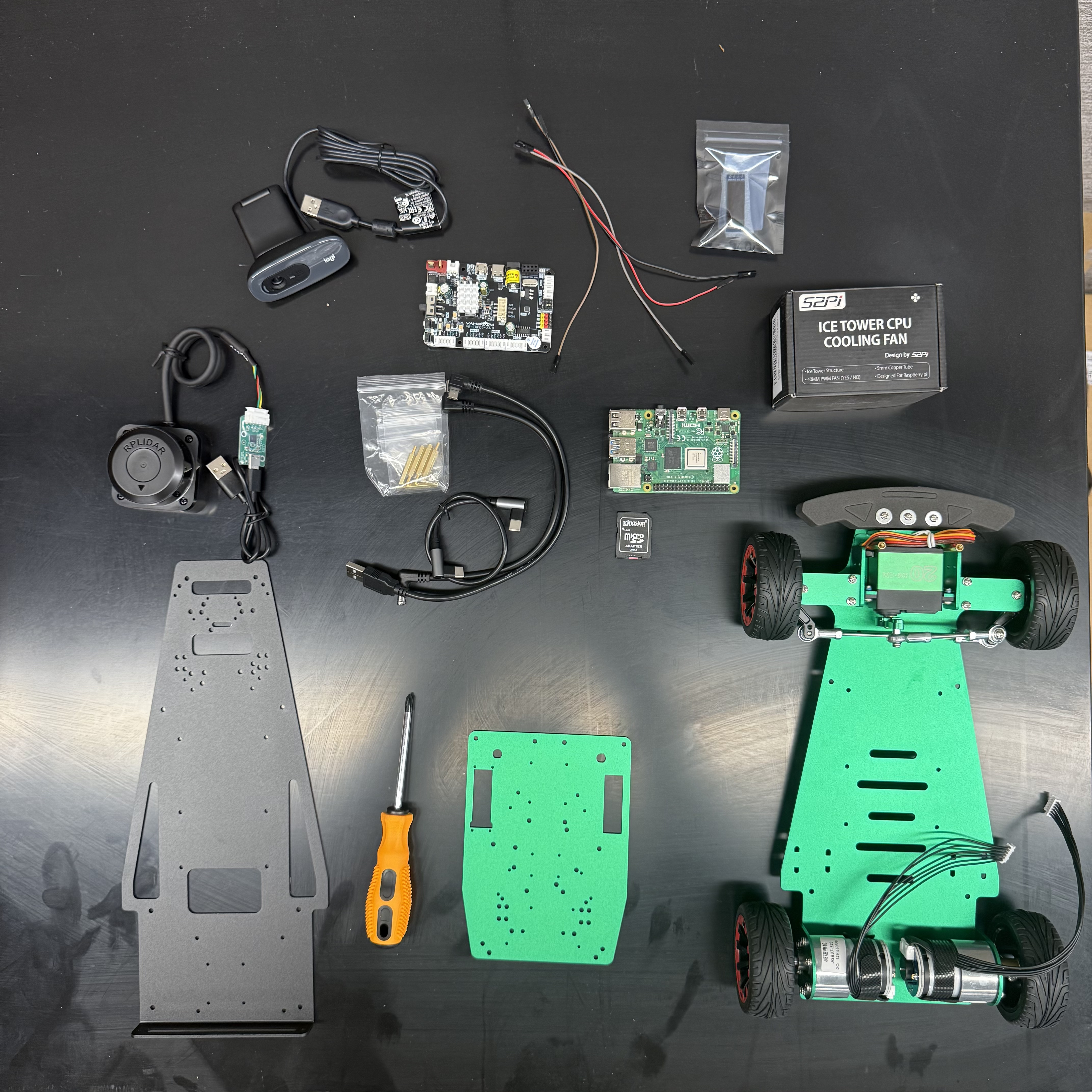
Find all the necessary parts in this Amazon list
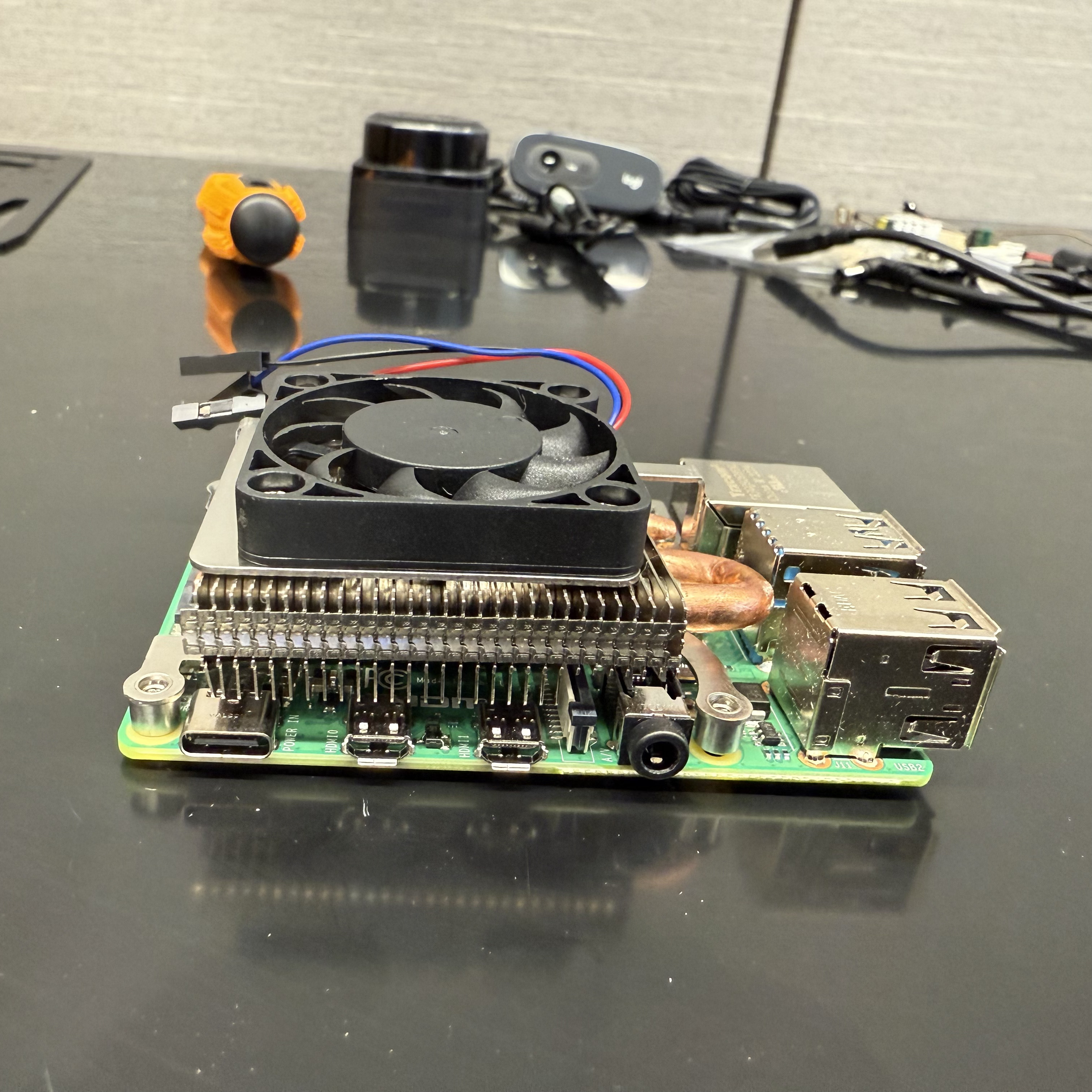
Step 1: Raspberry Pi and STM
Parts needed for this step:
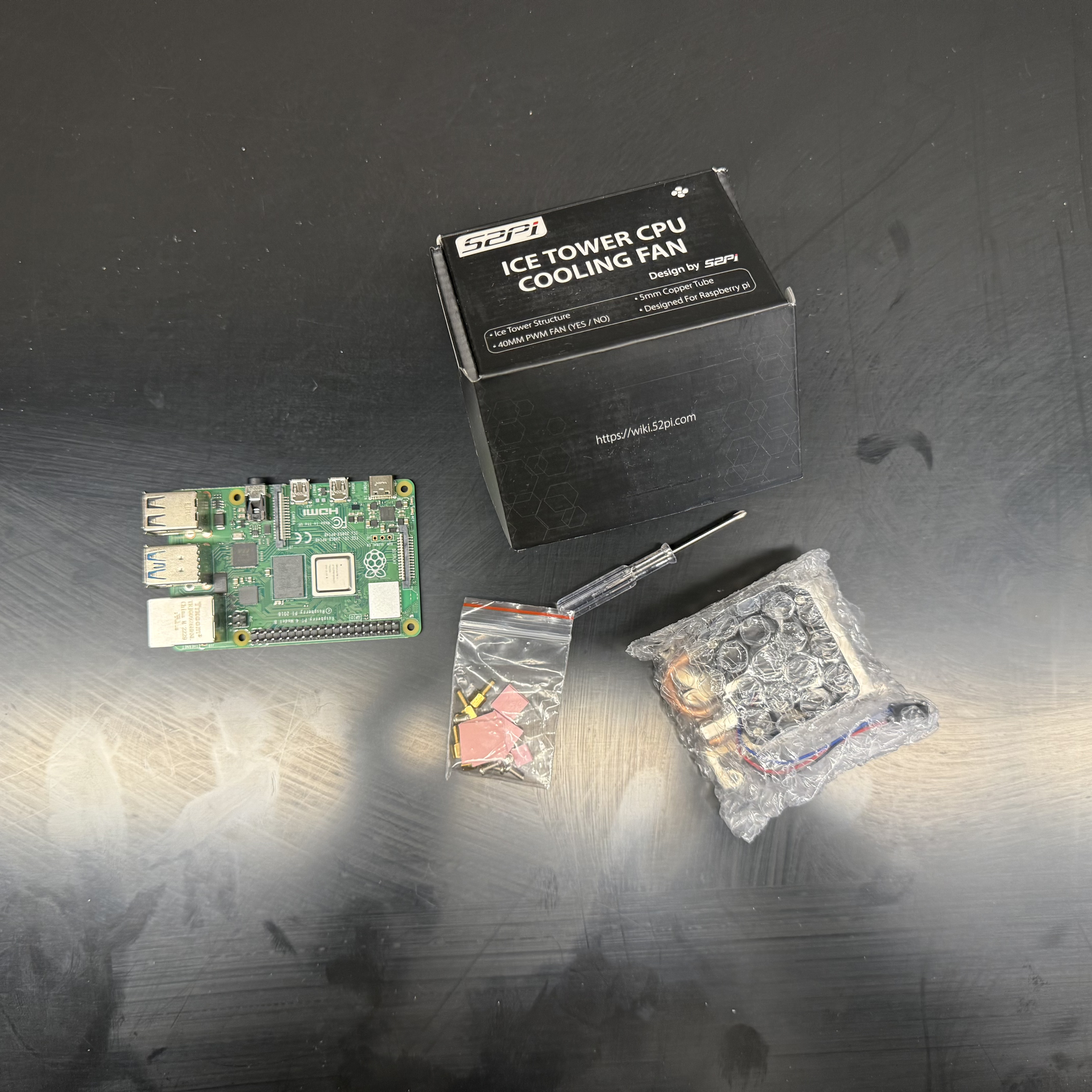
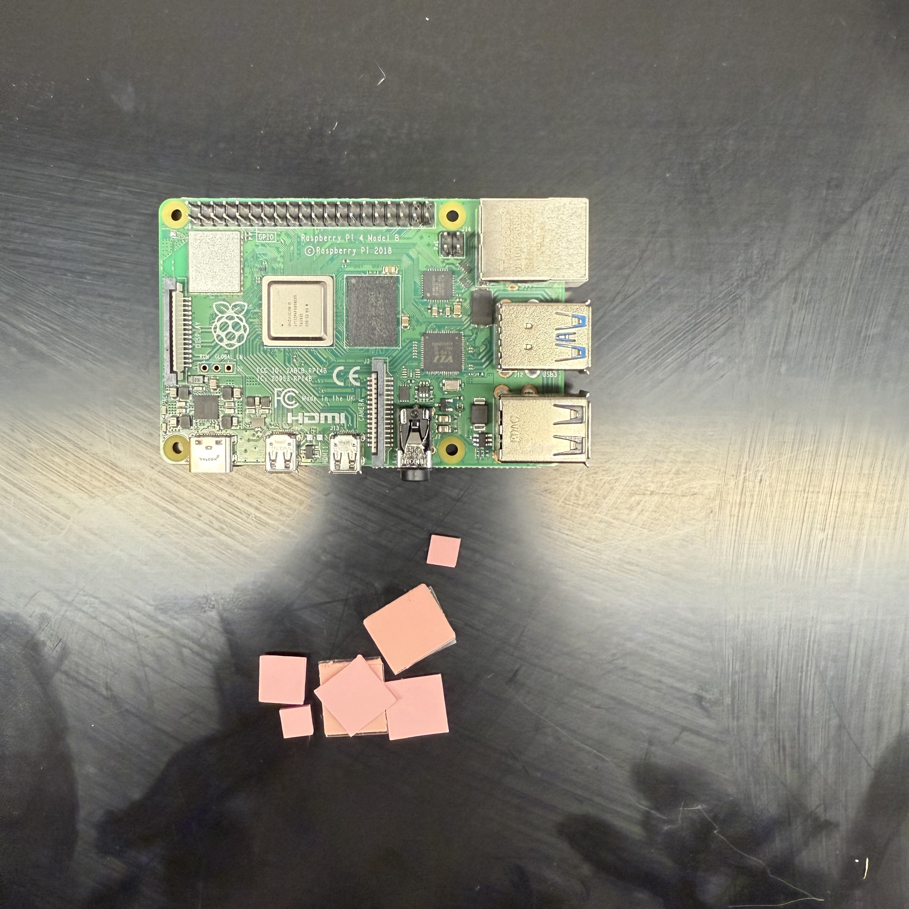
start by putting the stickers for heat sinks on the Raspberry Pi 4.
| Parts Needed | |
|---|---|
 |
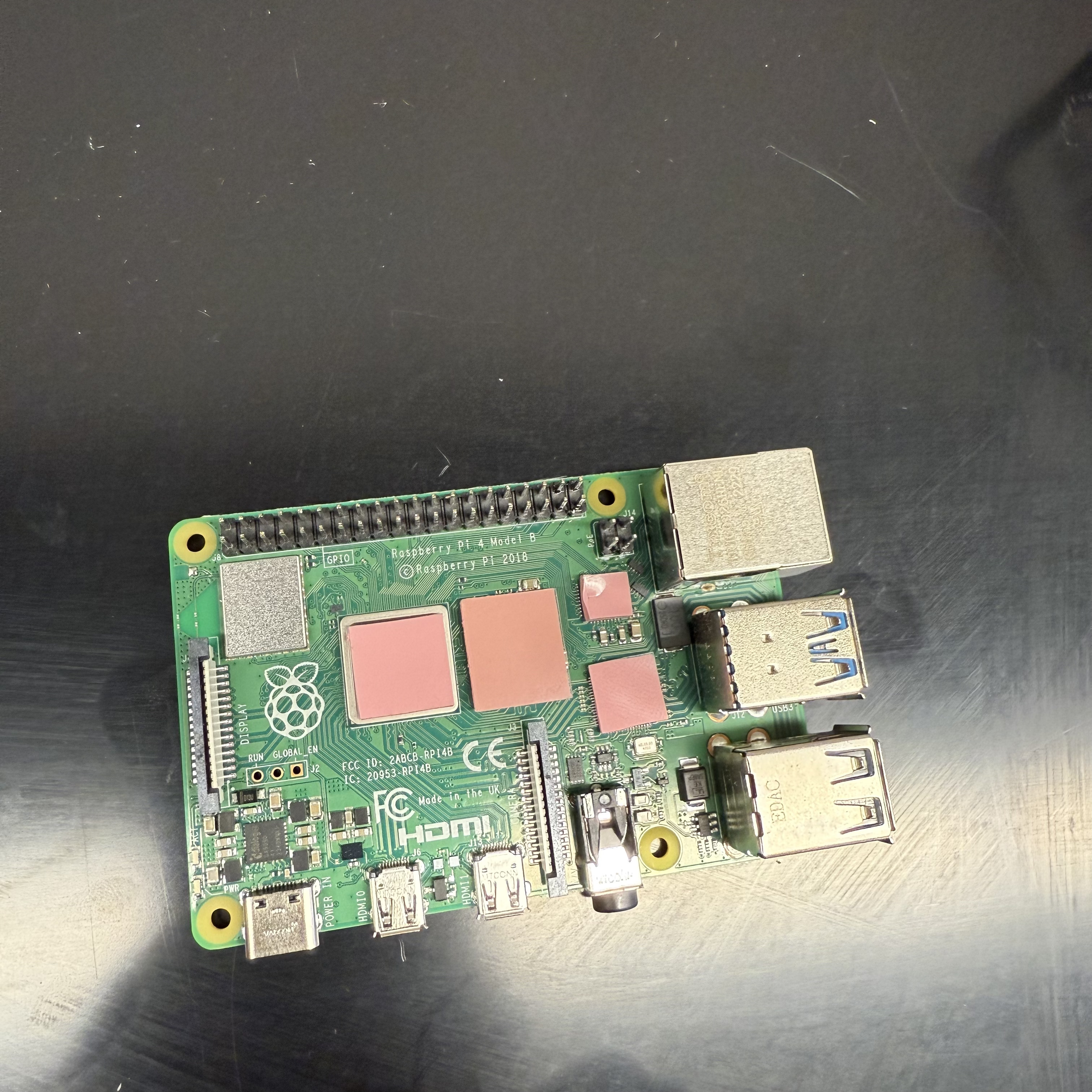 |
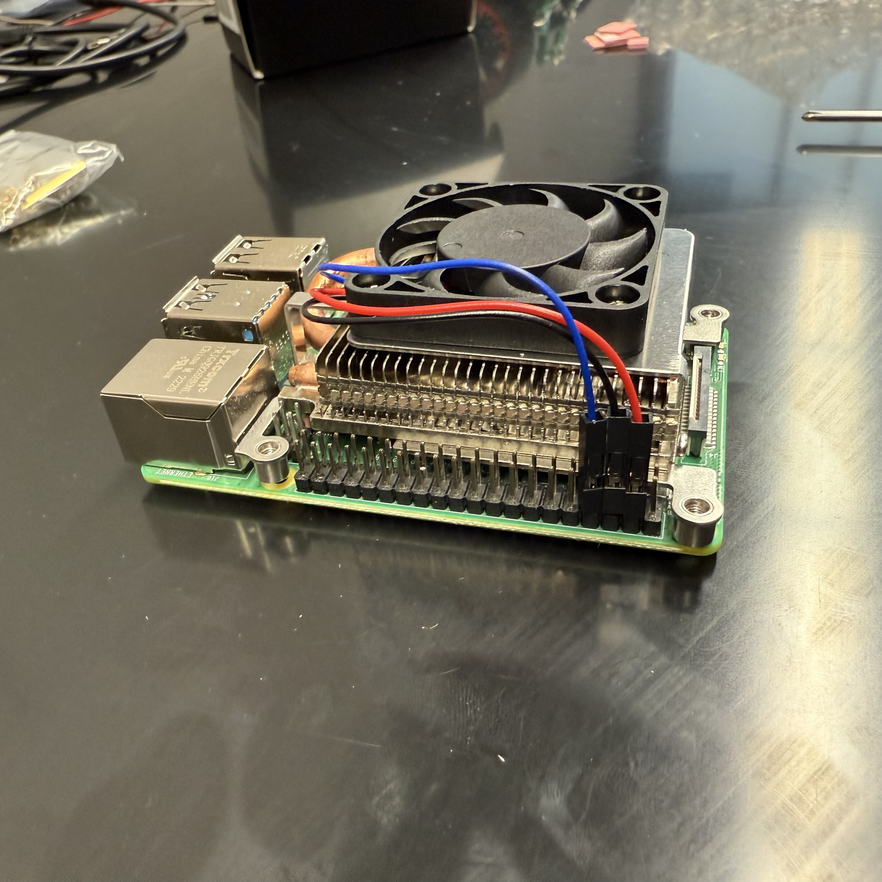
Attach the heat sinks to the Raspberry Pi 4.
 |
 |
 |
 |
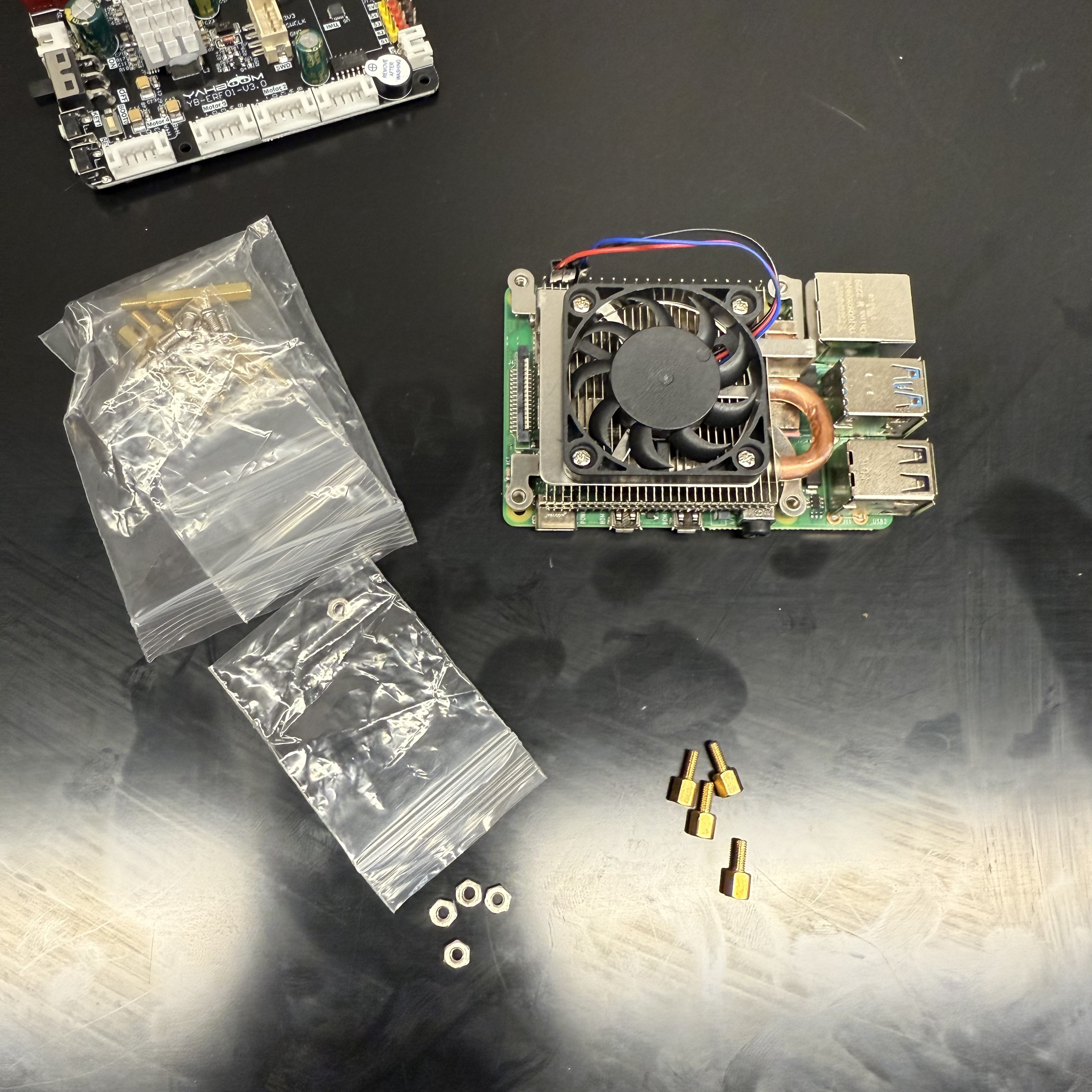
Using these parts:
 |
 |
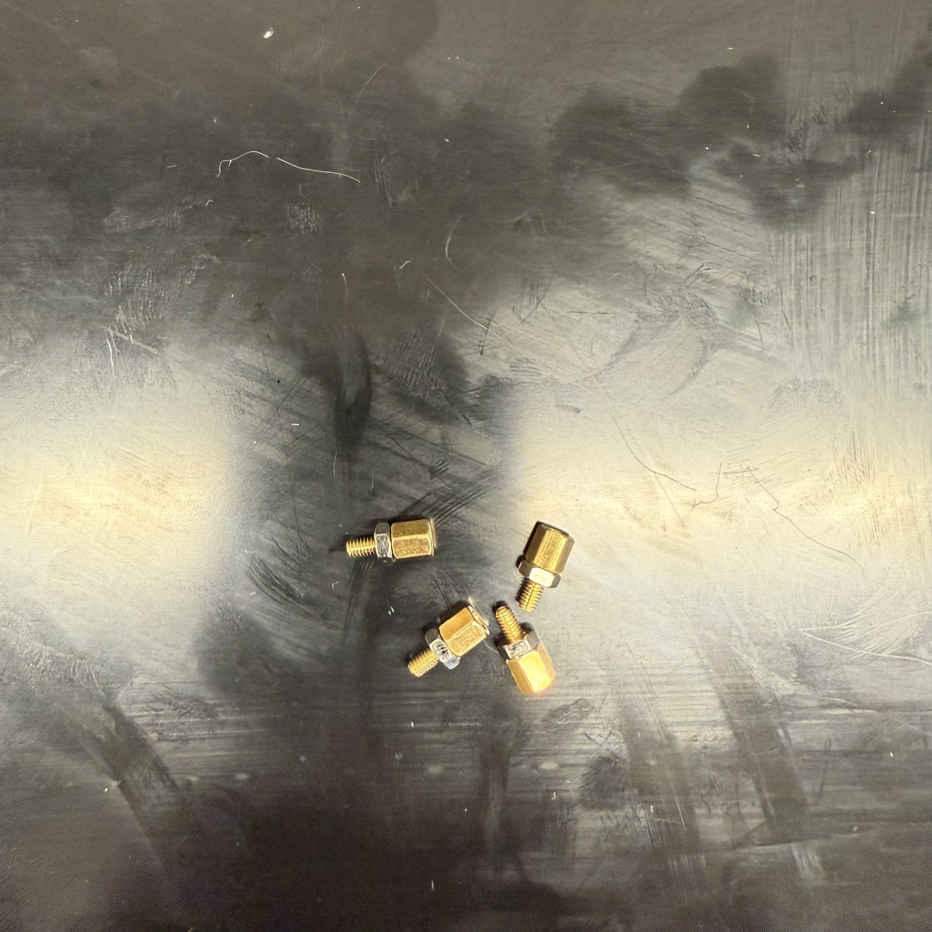 |
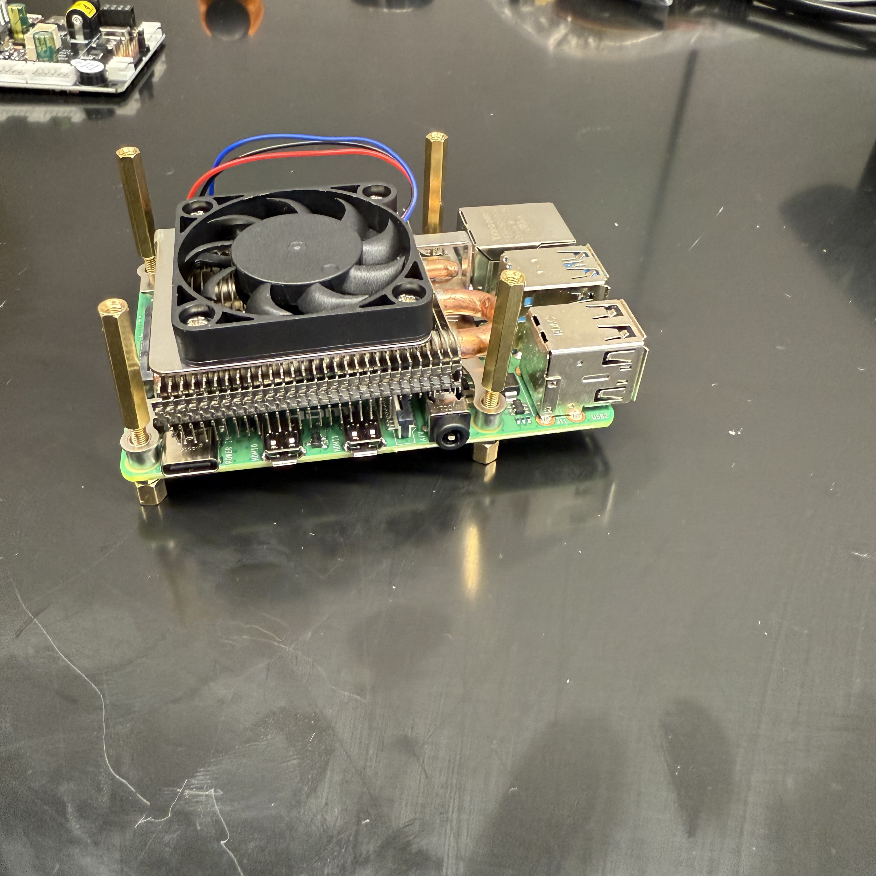
Skrew the Heat sink to the Raspberry Pi 4:
 |
 |
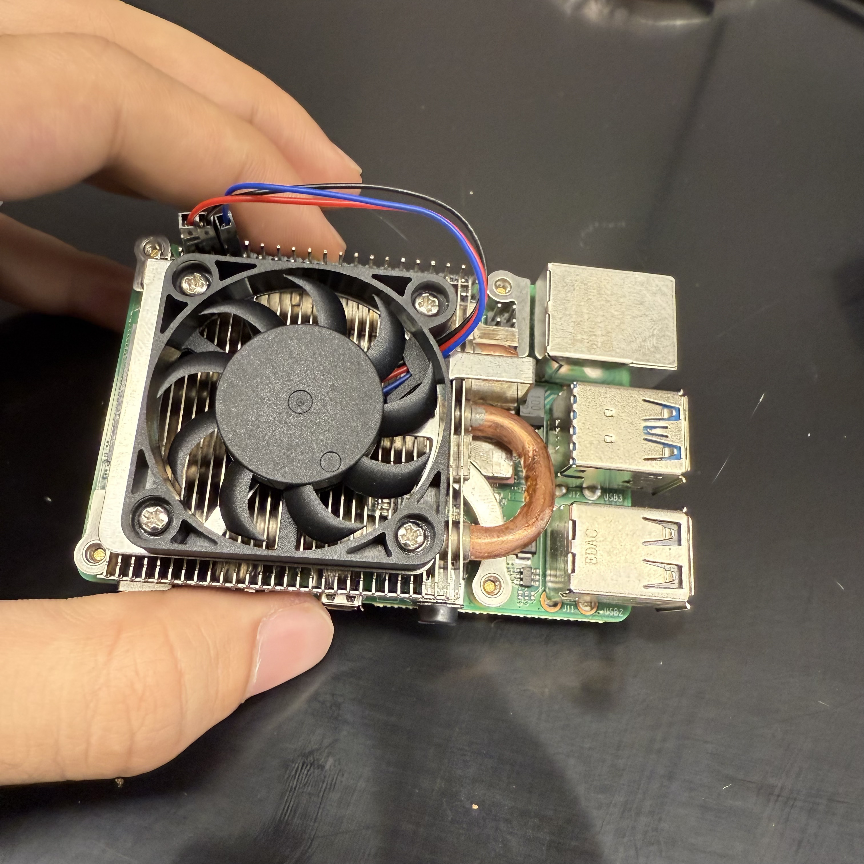 |
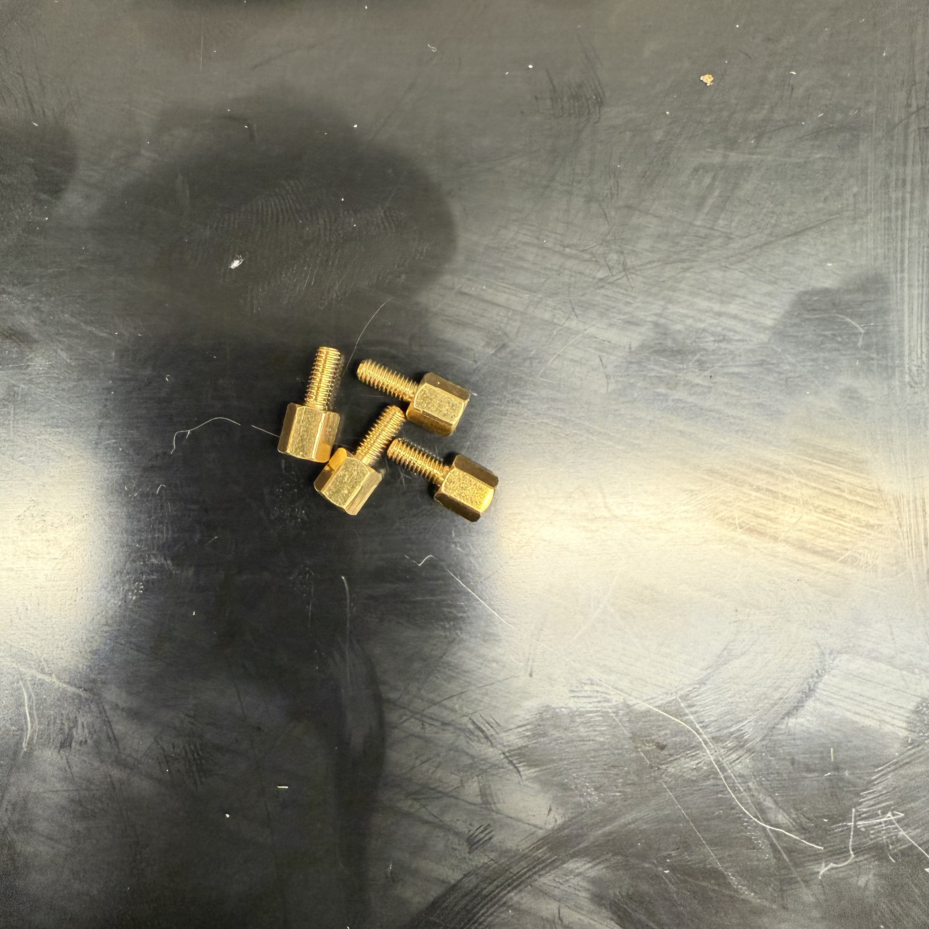
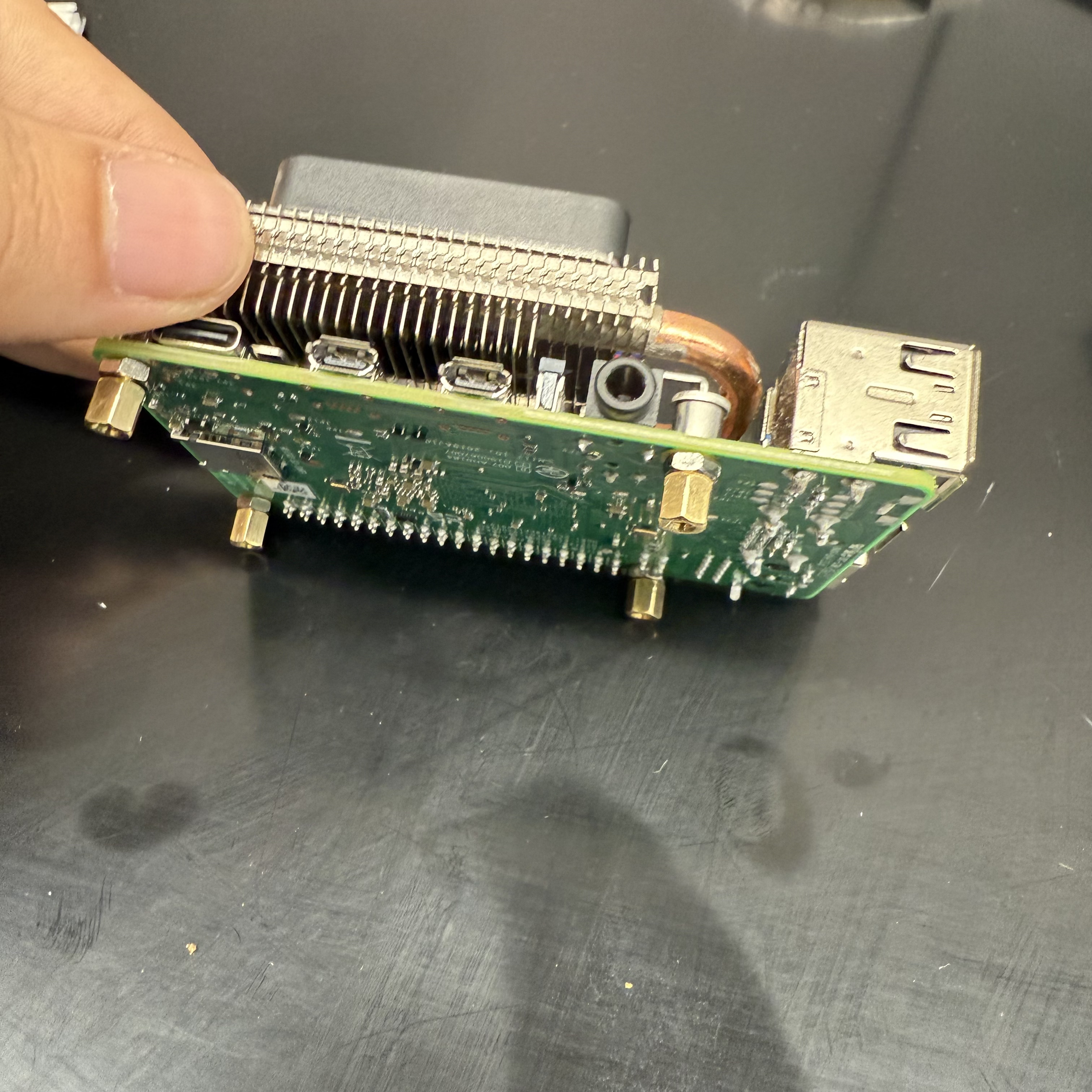
Add 4 x spacers to the raspberry pi 4:
| Spacers | ||
|---|---|---|
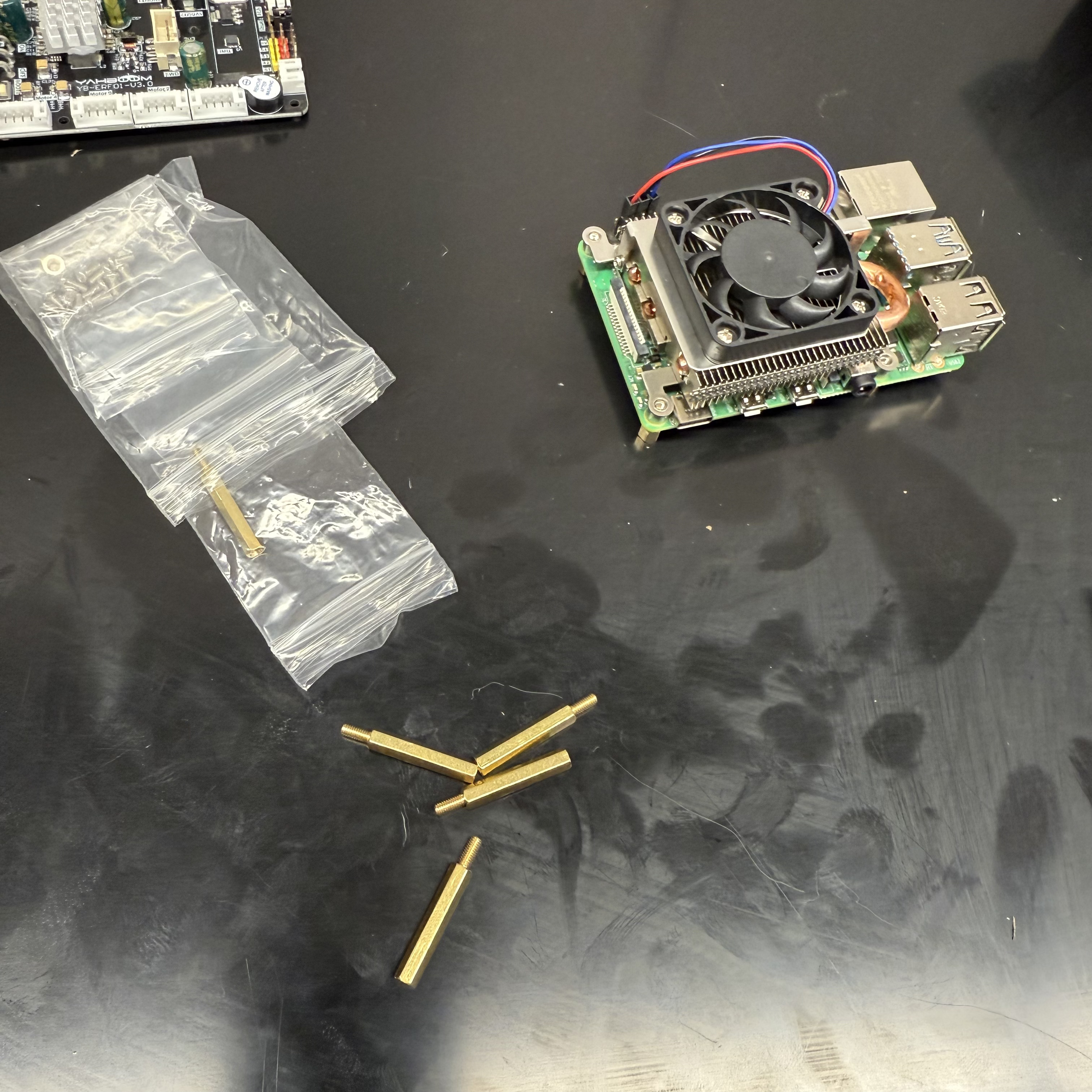 |
 |
 |
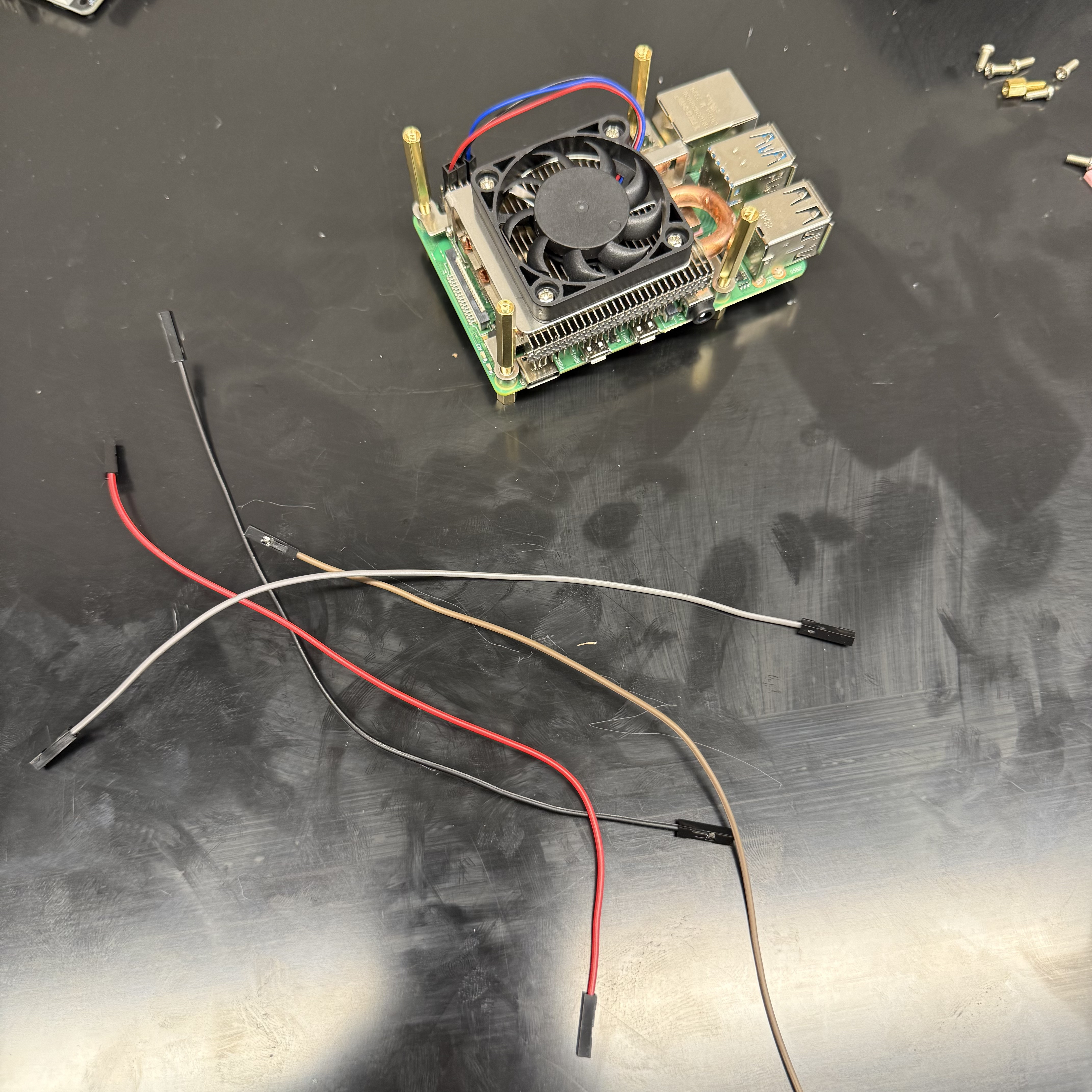
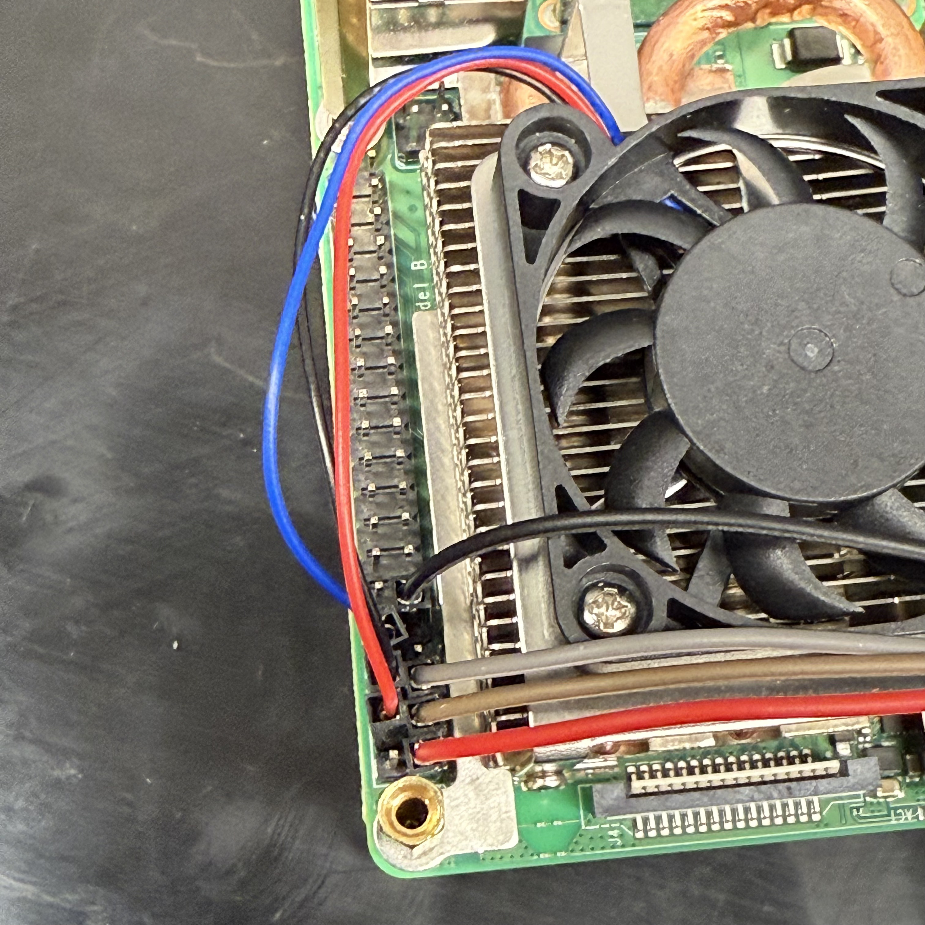
Connect the 4 x jumper wires to the GPIO pins on the Raspberry Pi 4:
| Jumper Wires | ||
|---|---|---|
 |
 |
 |
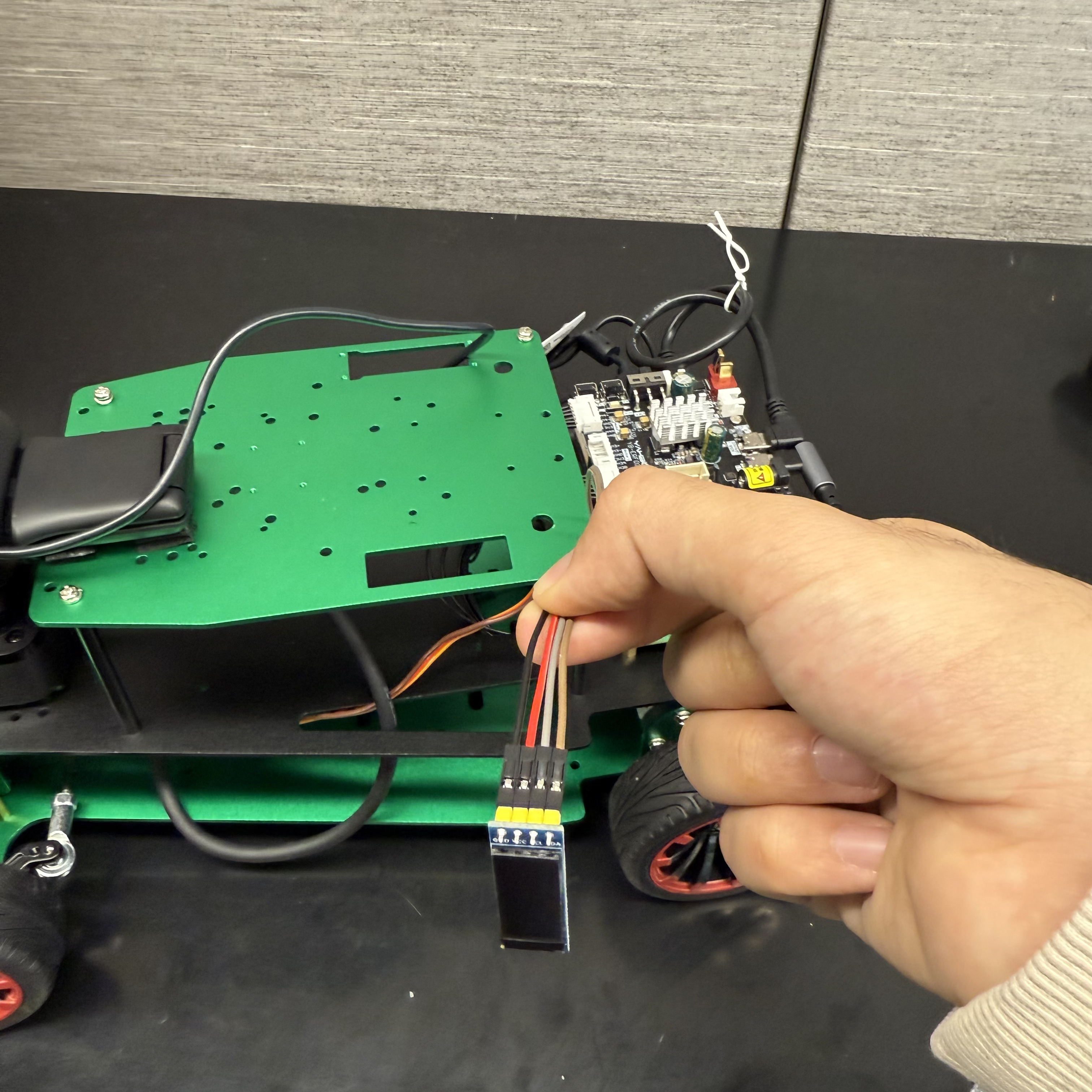
Wires pins (pinout ref):
- red -> 5V (pin 1)
- black -> GND (pin 9)
- brown -> SDA (pin 3)
- white -> SCL (pin 5)
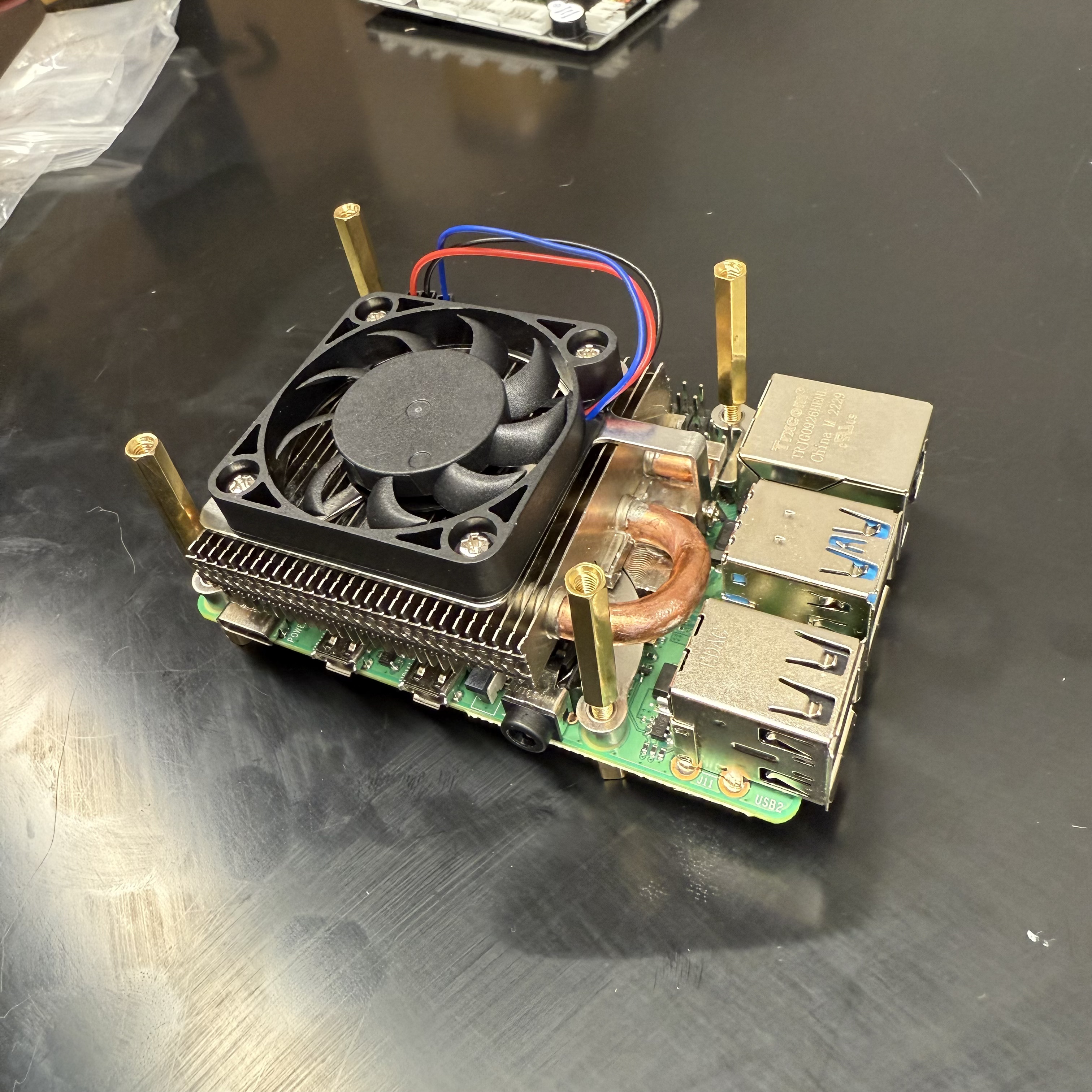
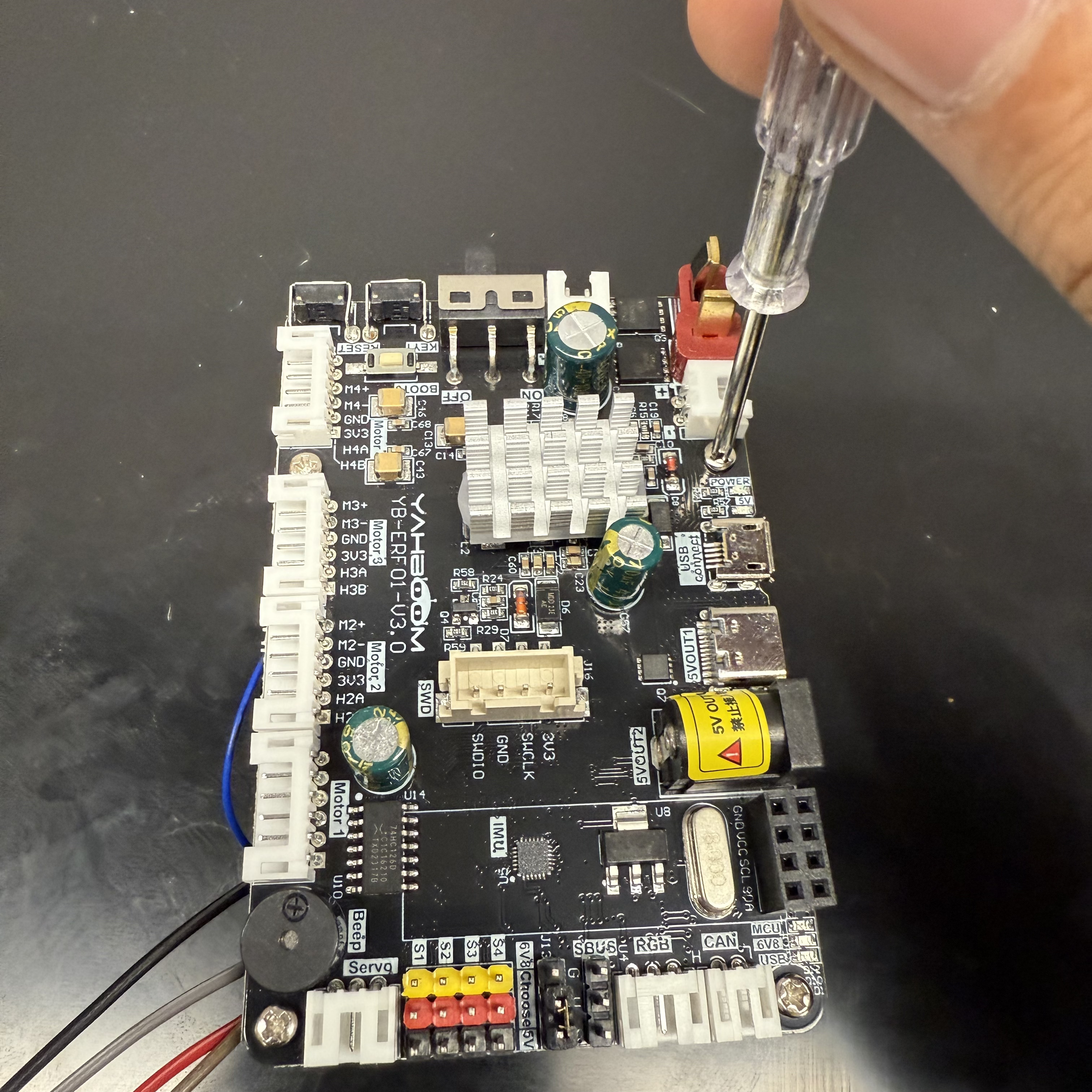
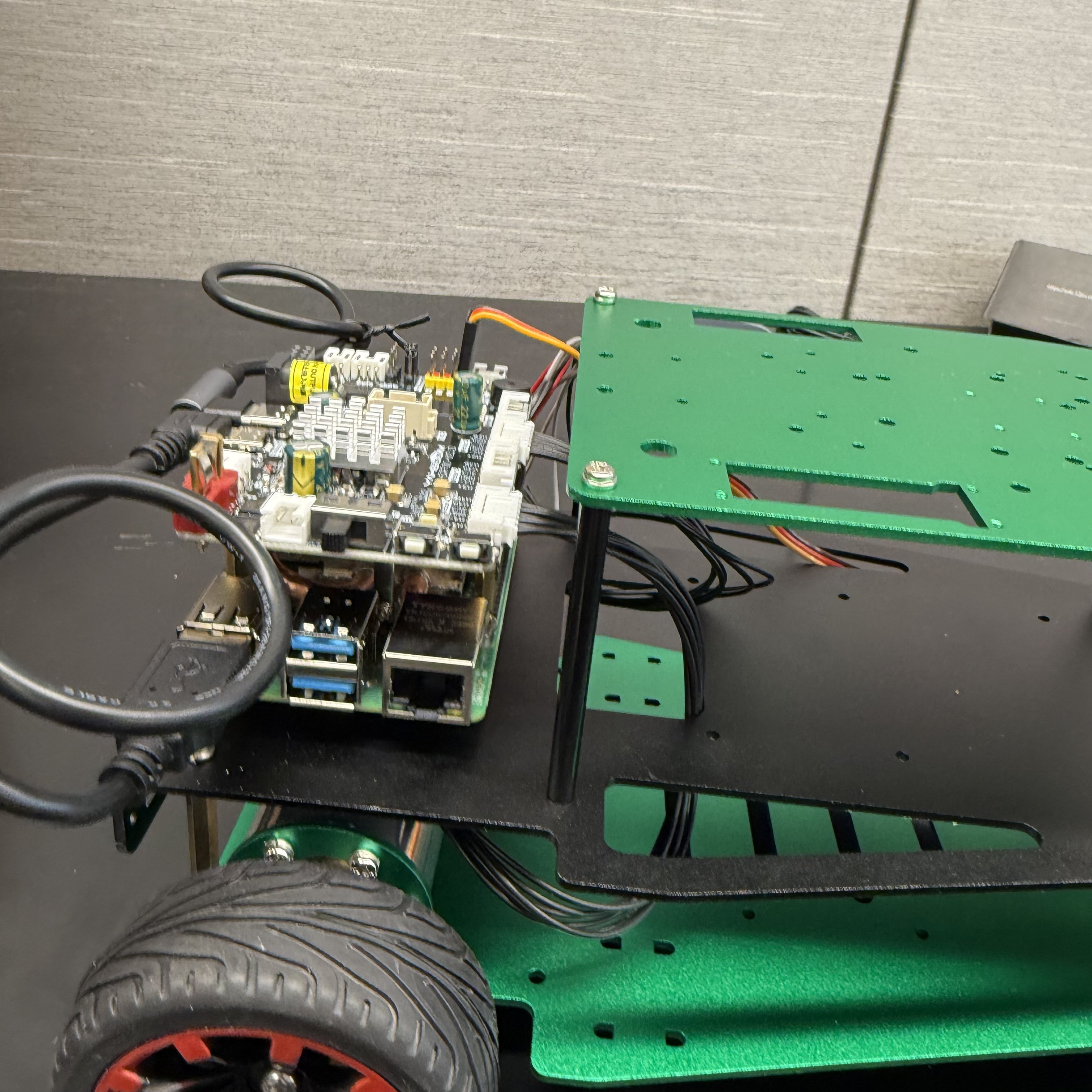
Place the STM 32F4 Discovery Board on top of the Raspberry Pi 4:
Then screw the STM 32F4 Discovery Board to the Raspberry Pi 4:
| Parts Needed | |
|---|---|
 |
 |
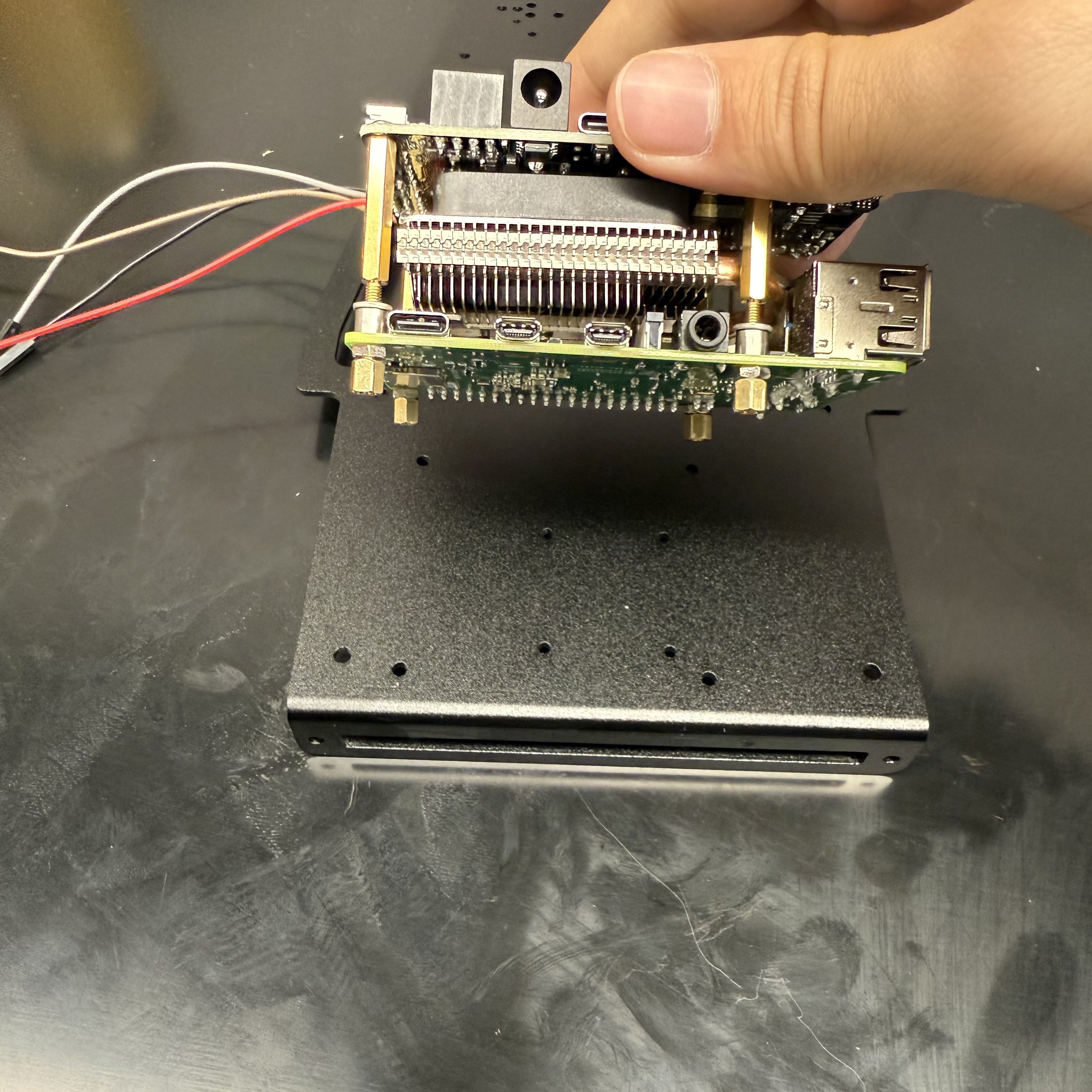
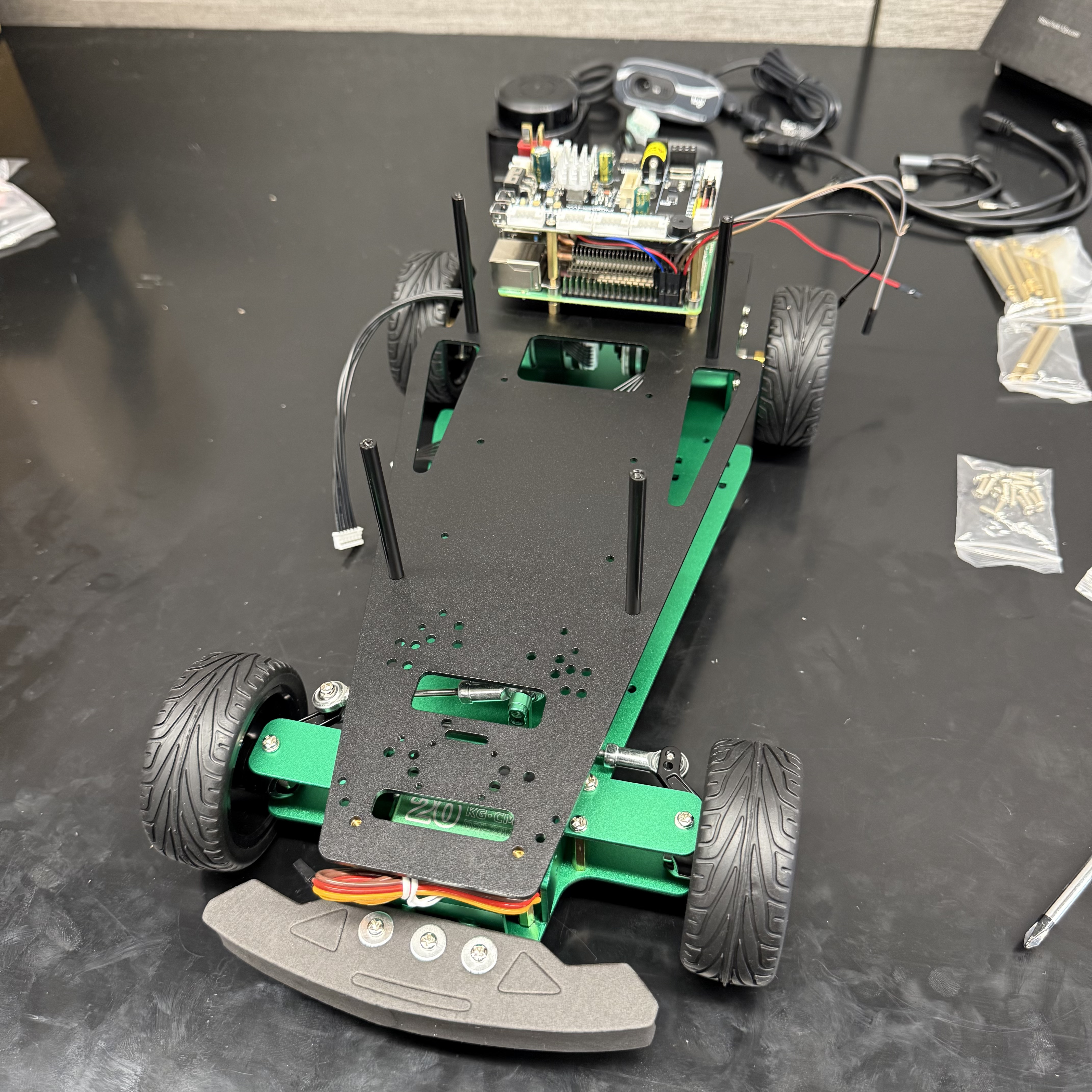
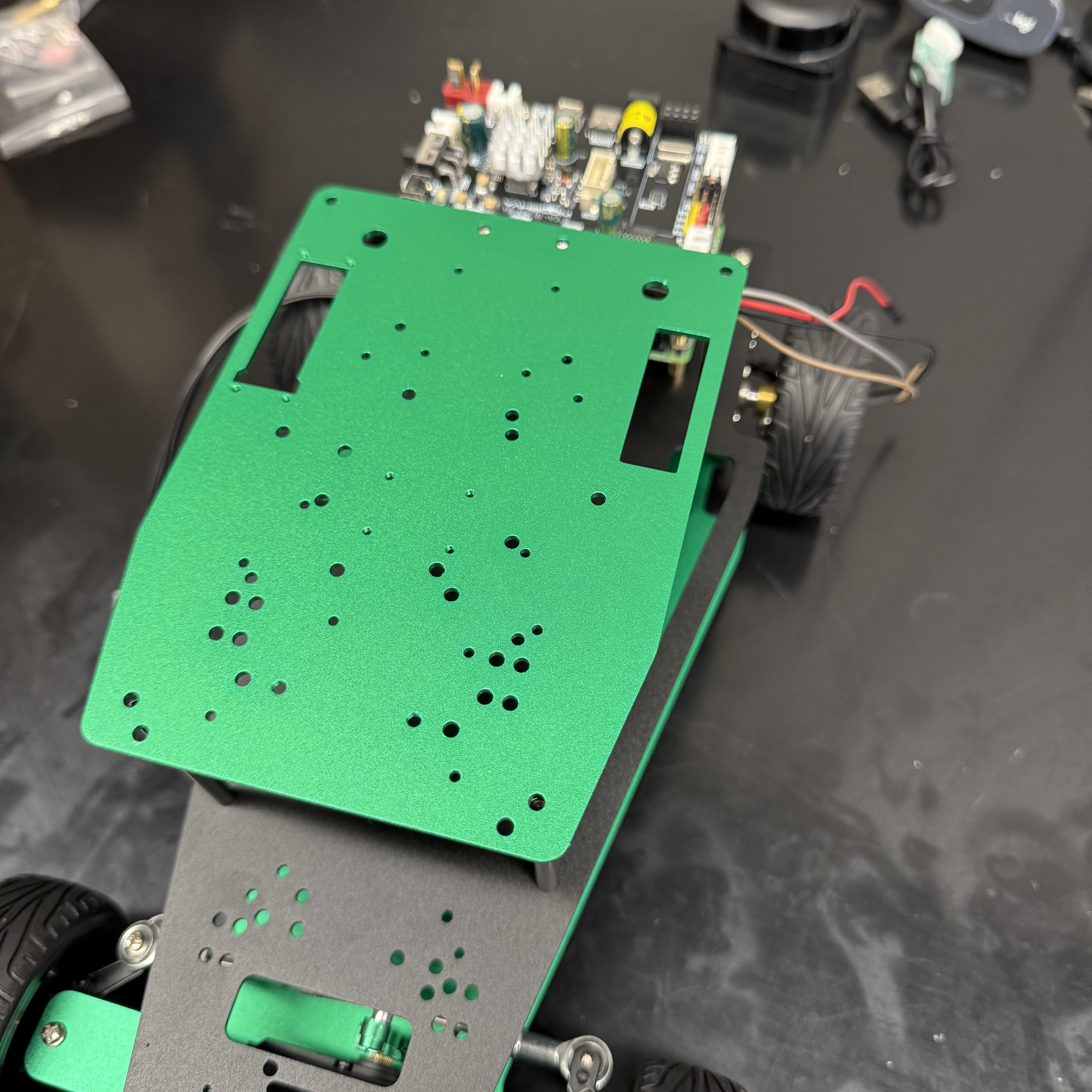
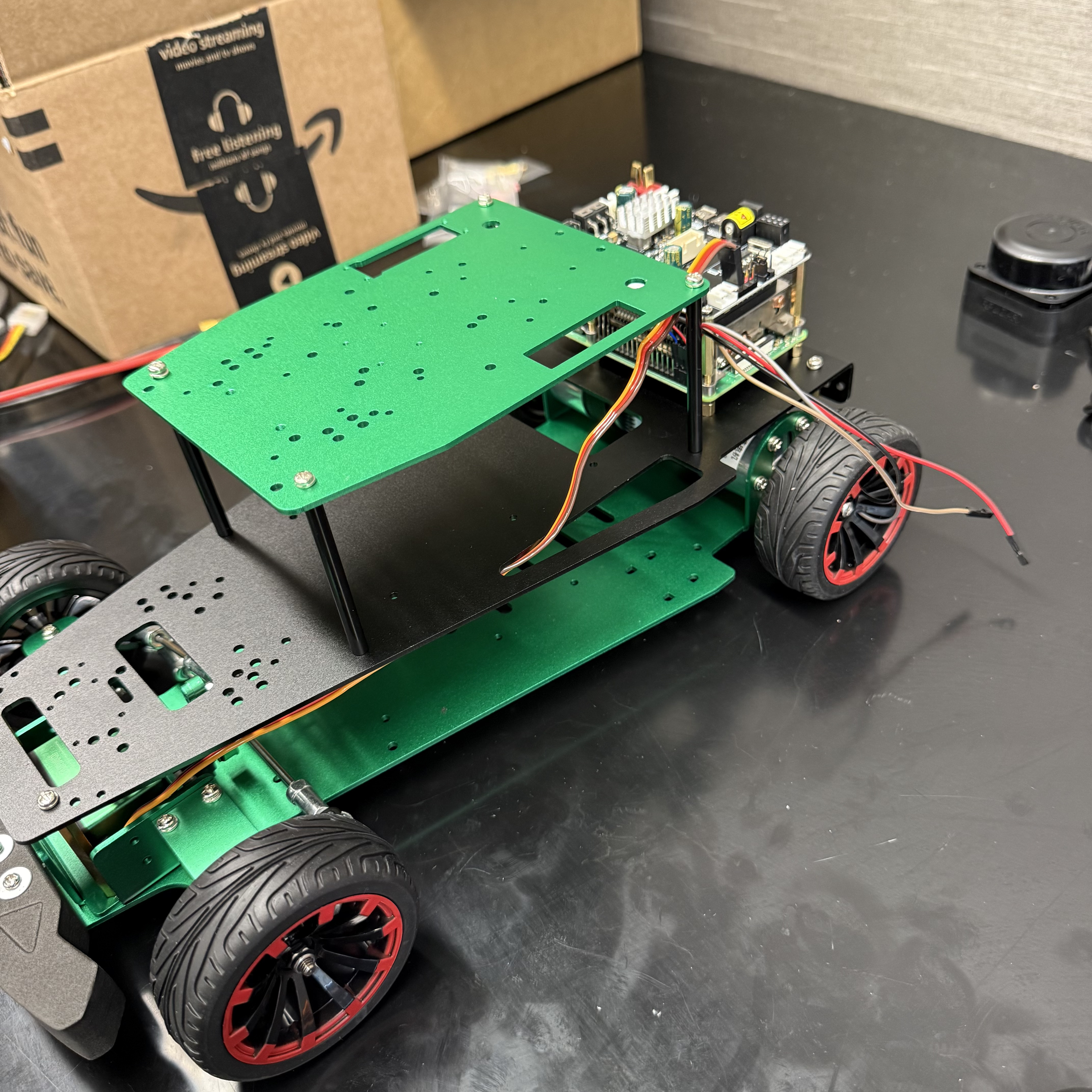
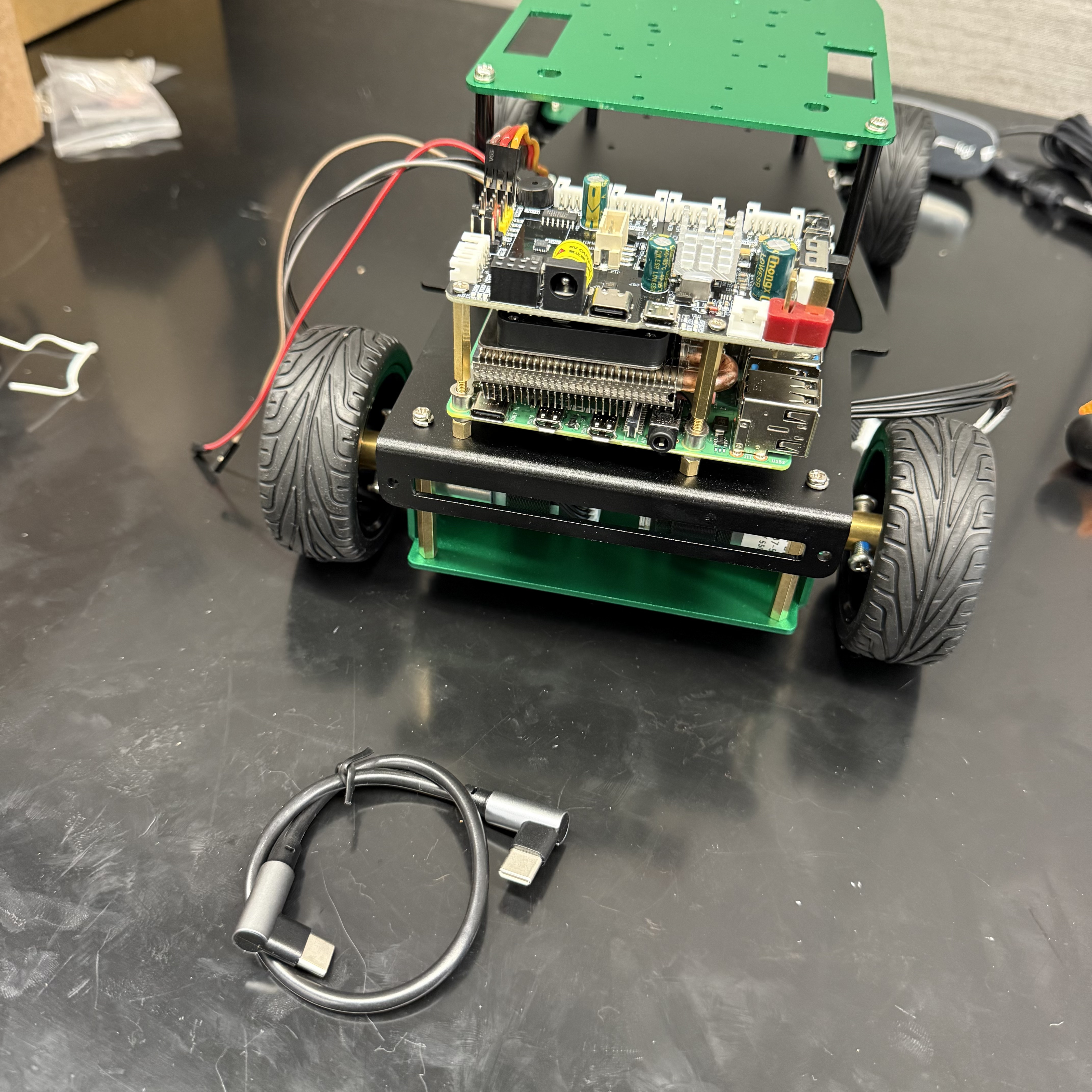
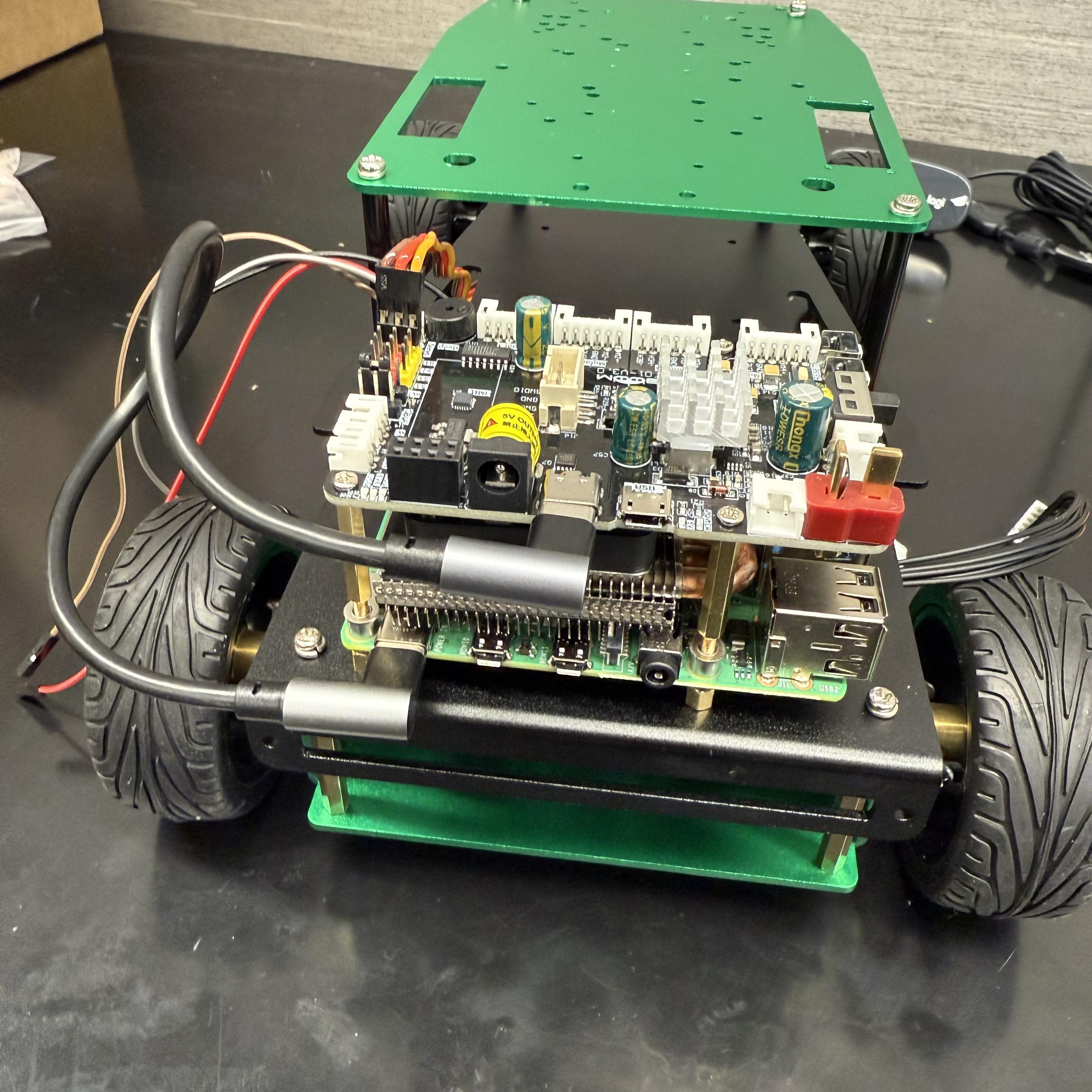
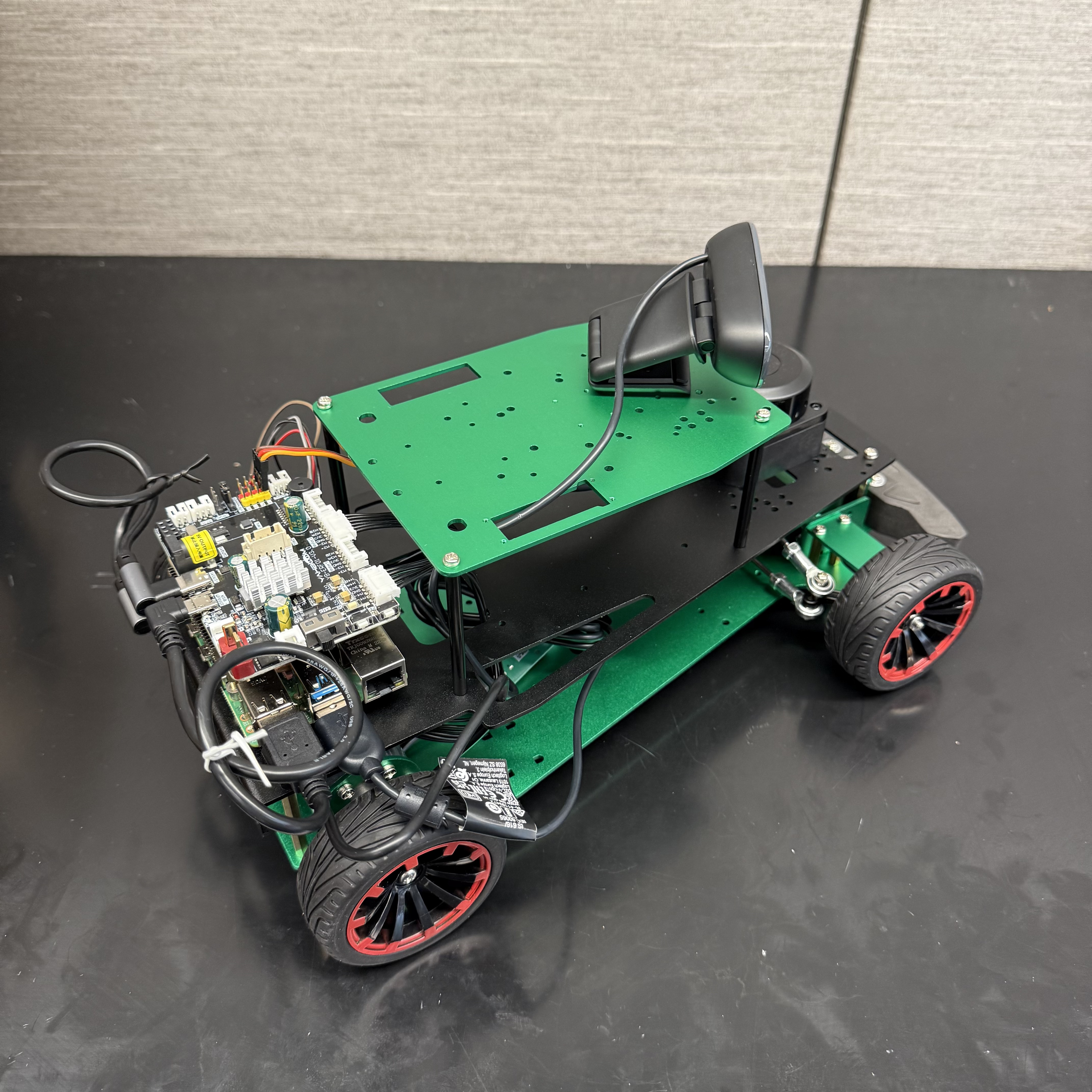
Finally mount the Raspberry Pi 4 and STM 32F4 Discovery Board to the chassis:
| Parts Needed | |
|---|---|
 |
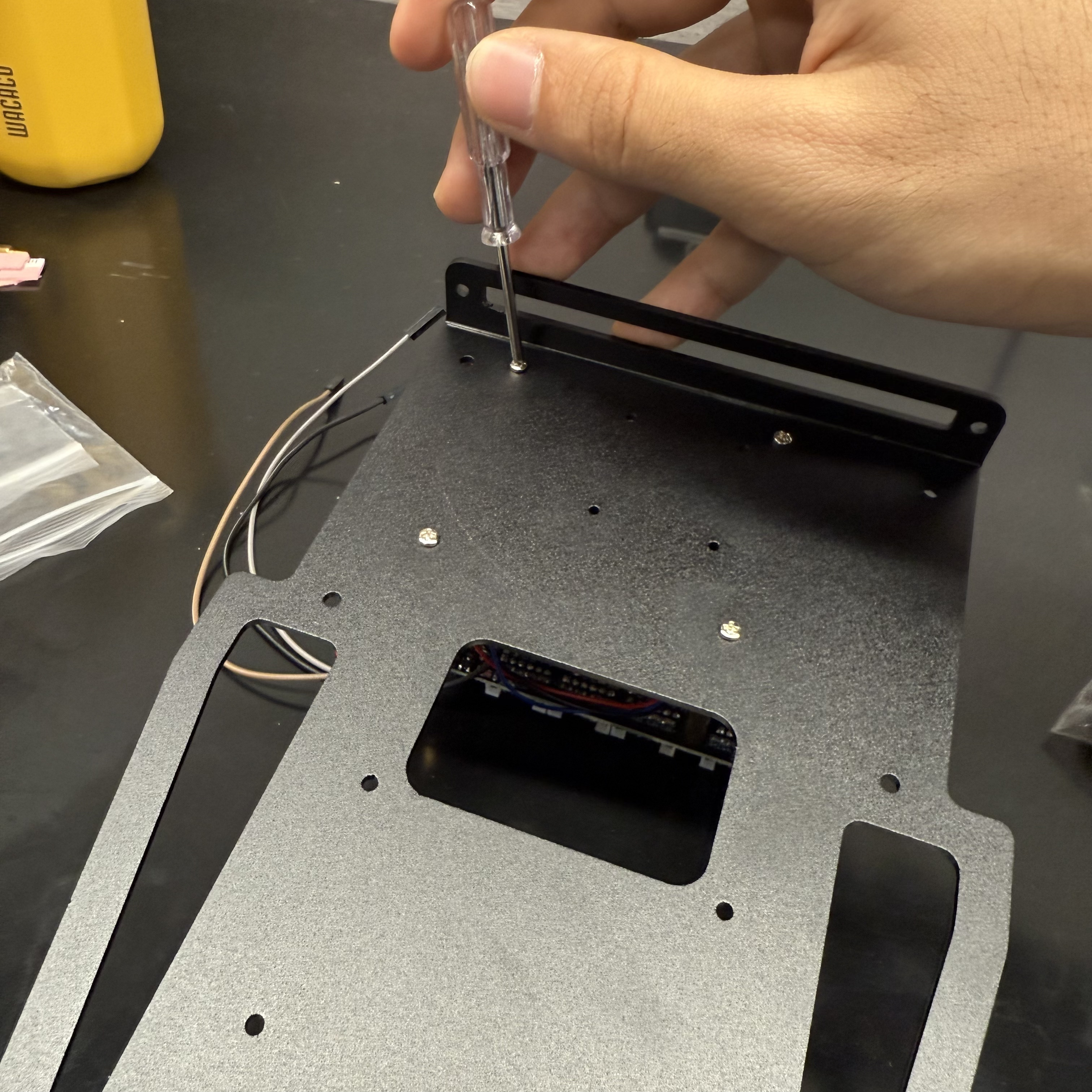 |
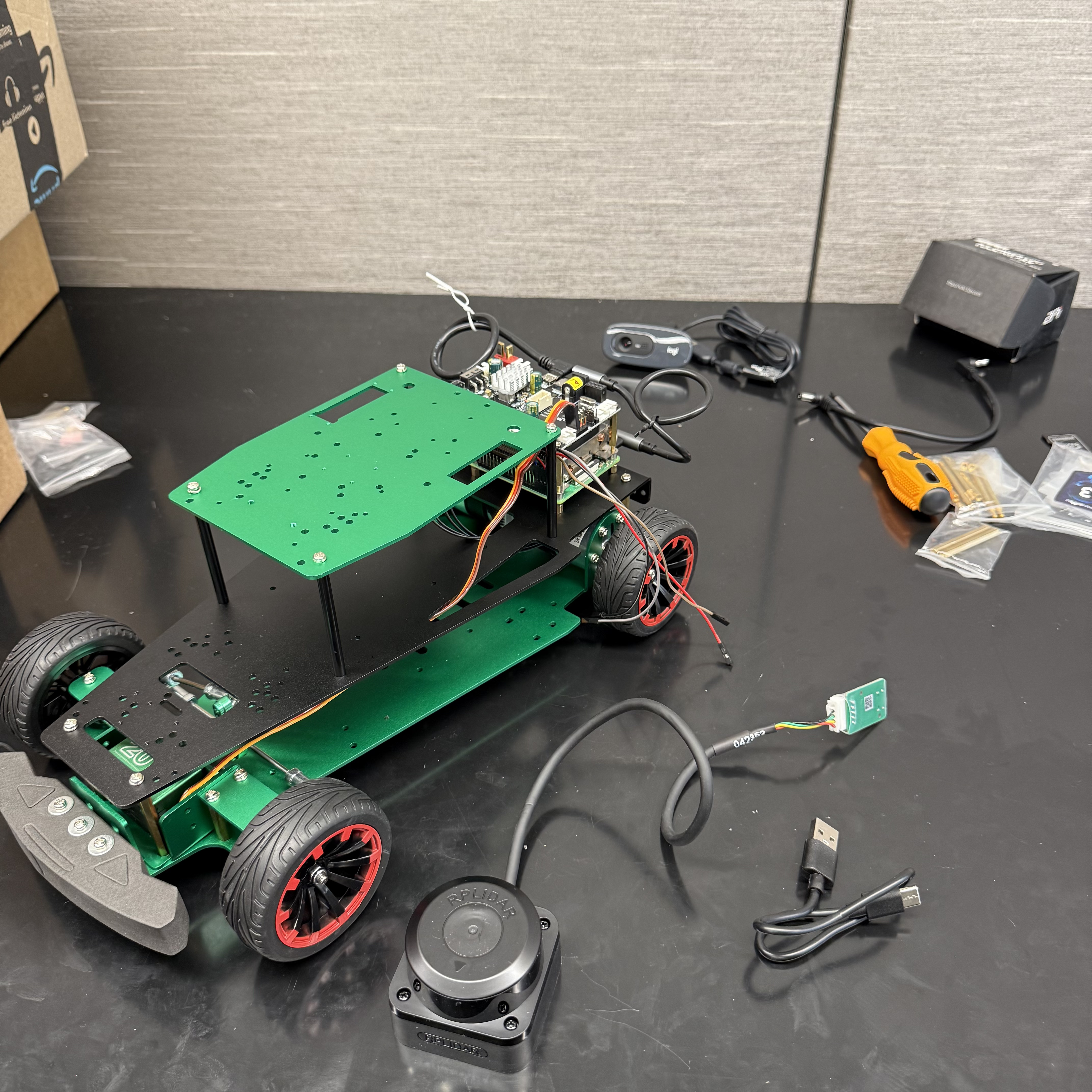
The final result should look like this:
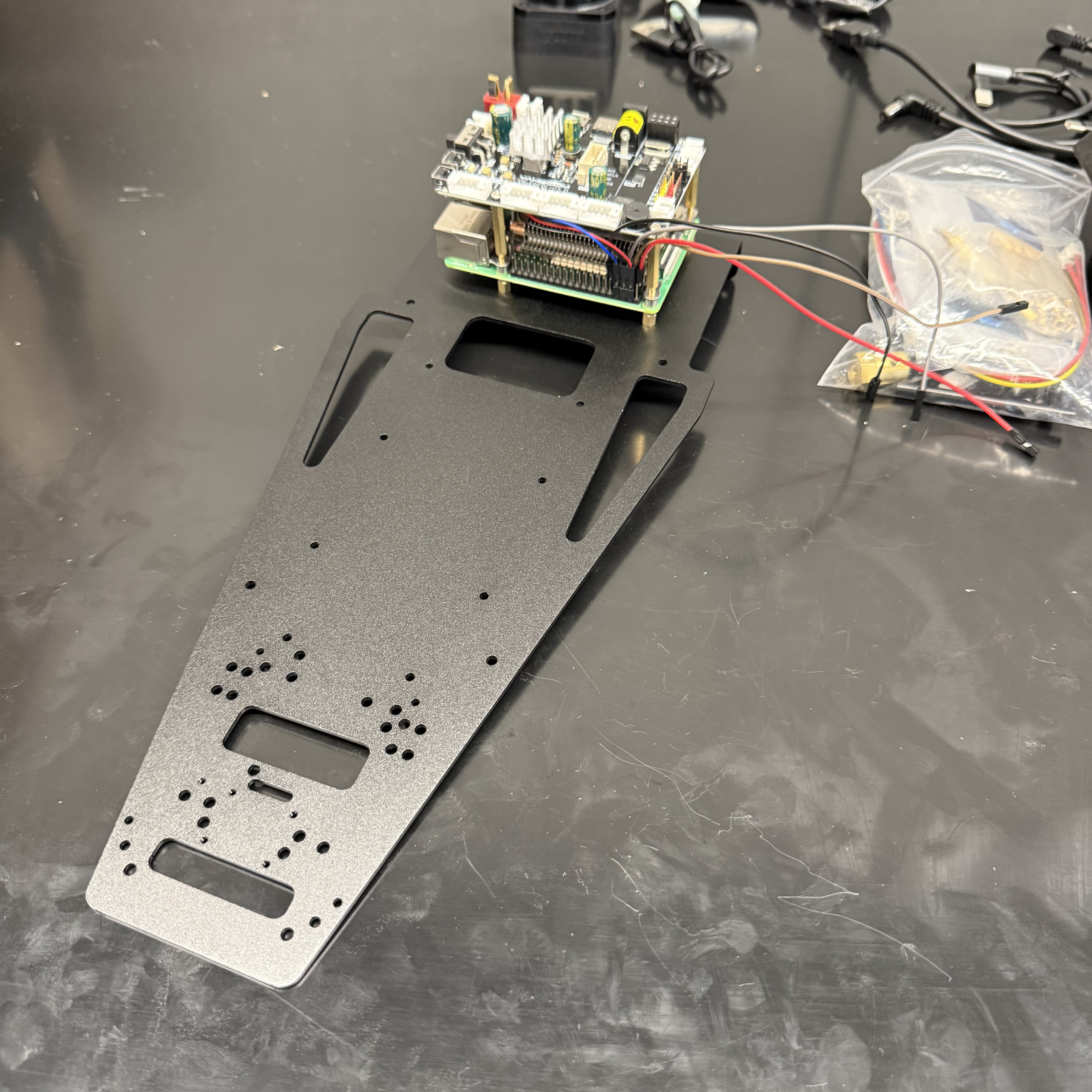
Step 2: Chassis Assembly
Parts needed for this step:
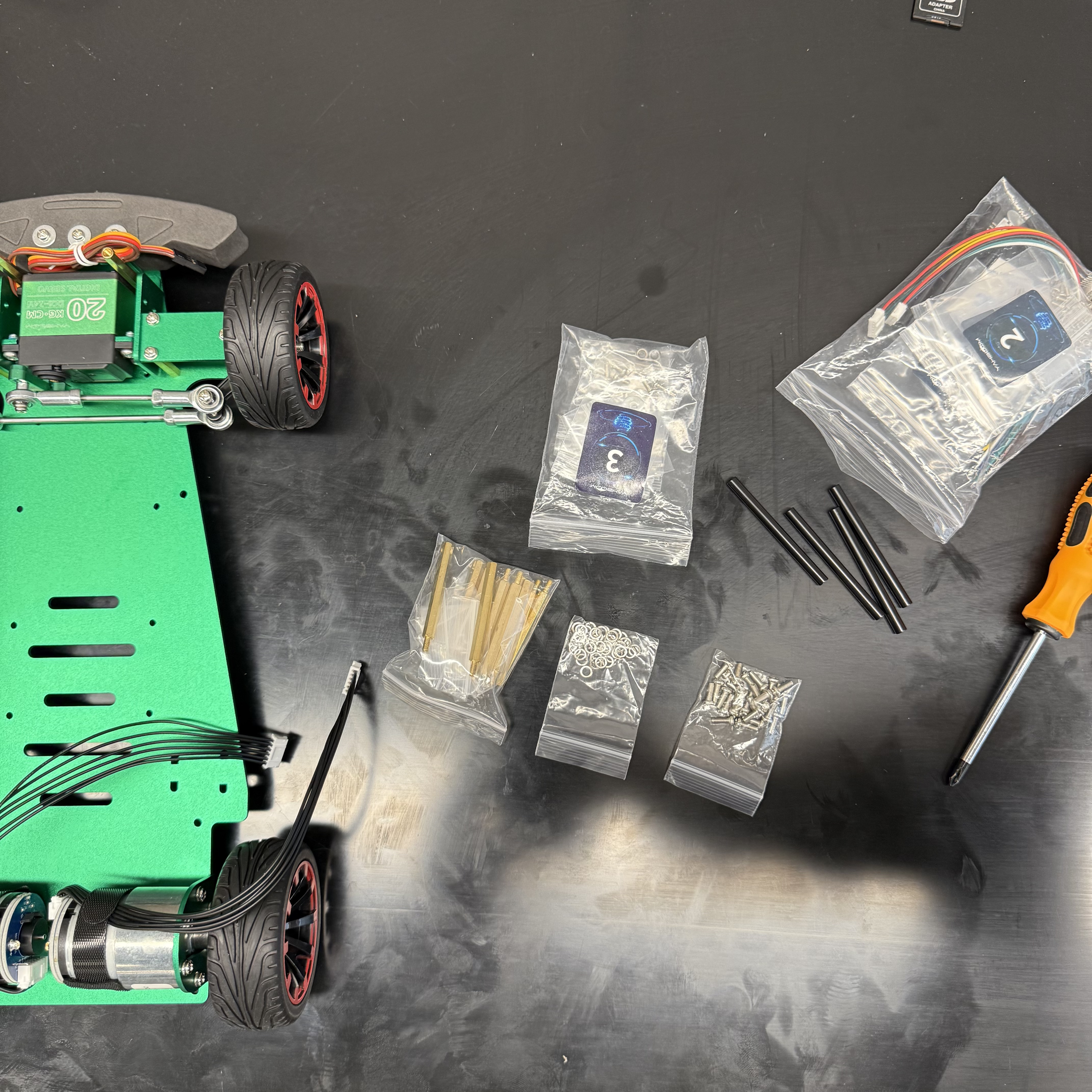
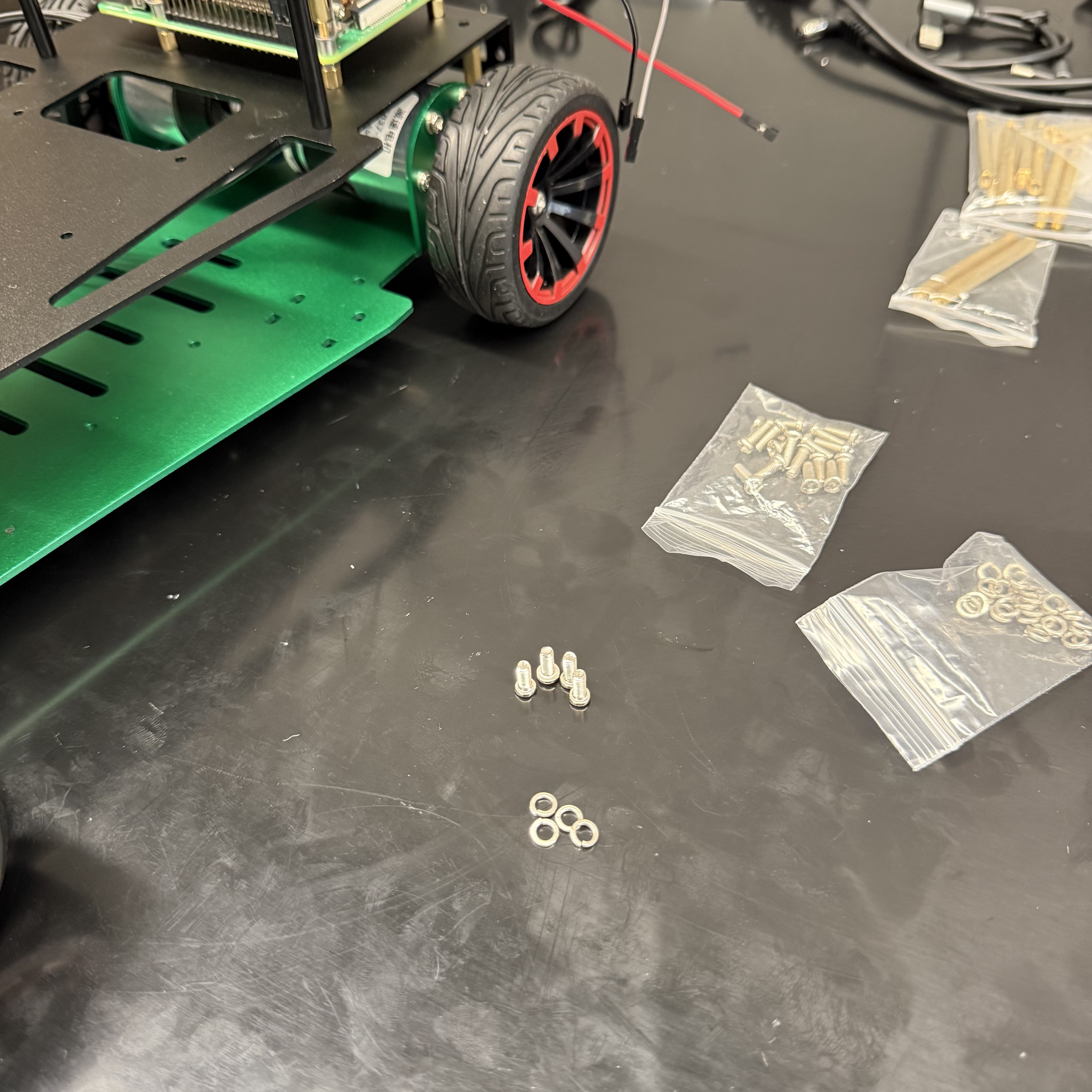
Add 2 x spacers to the chassis base:
| Parts Needed | |
|---|---|
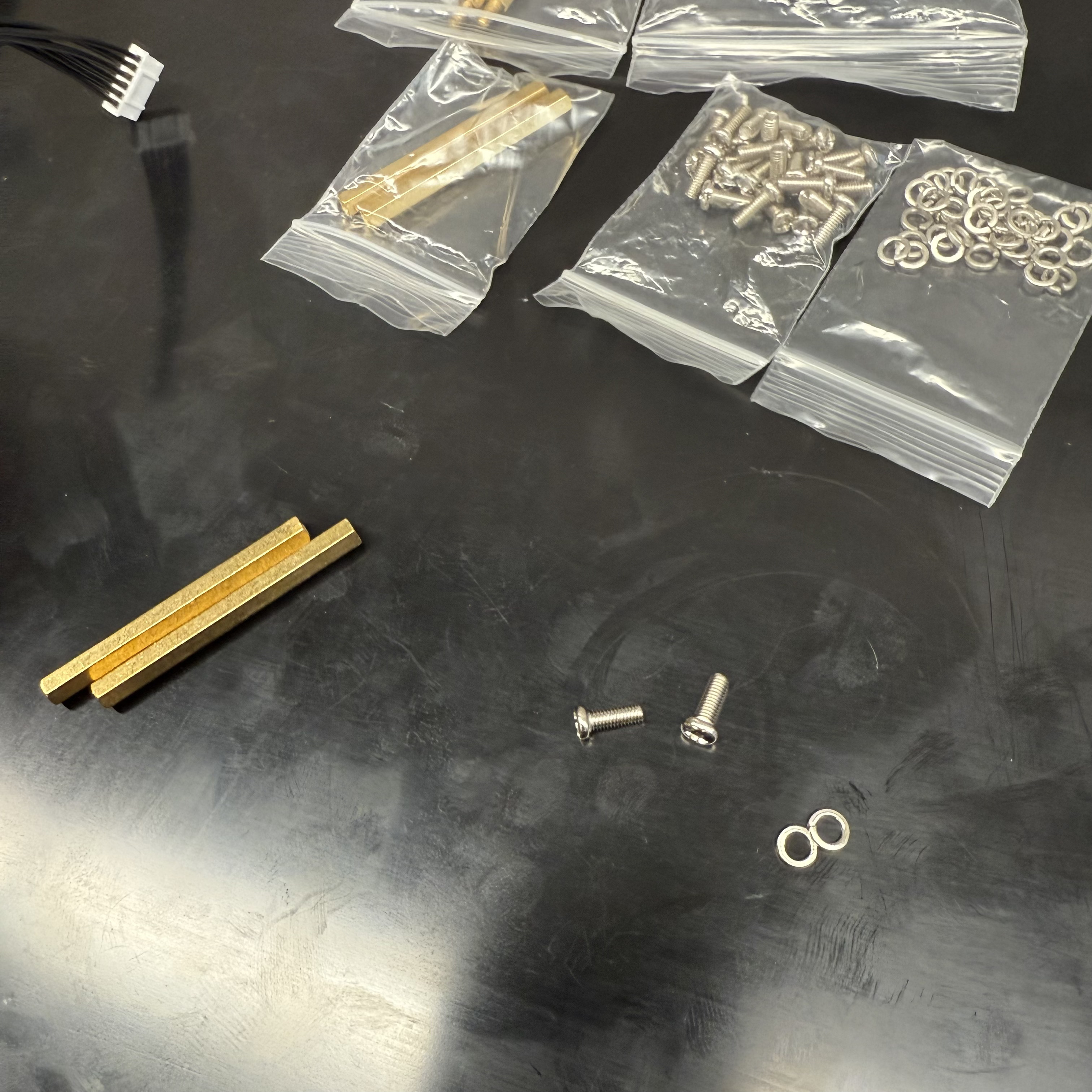 |
 |
Add 2 x spacers to the black plate:
| Parts Needed | |
|---|---|
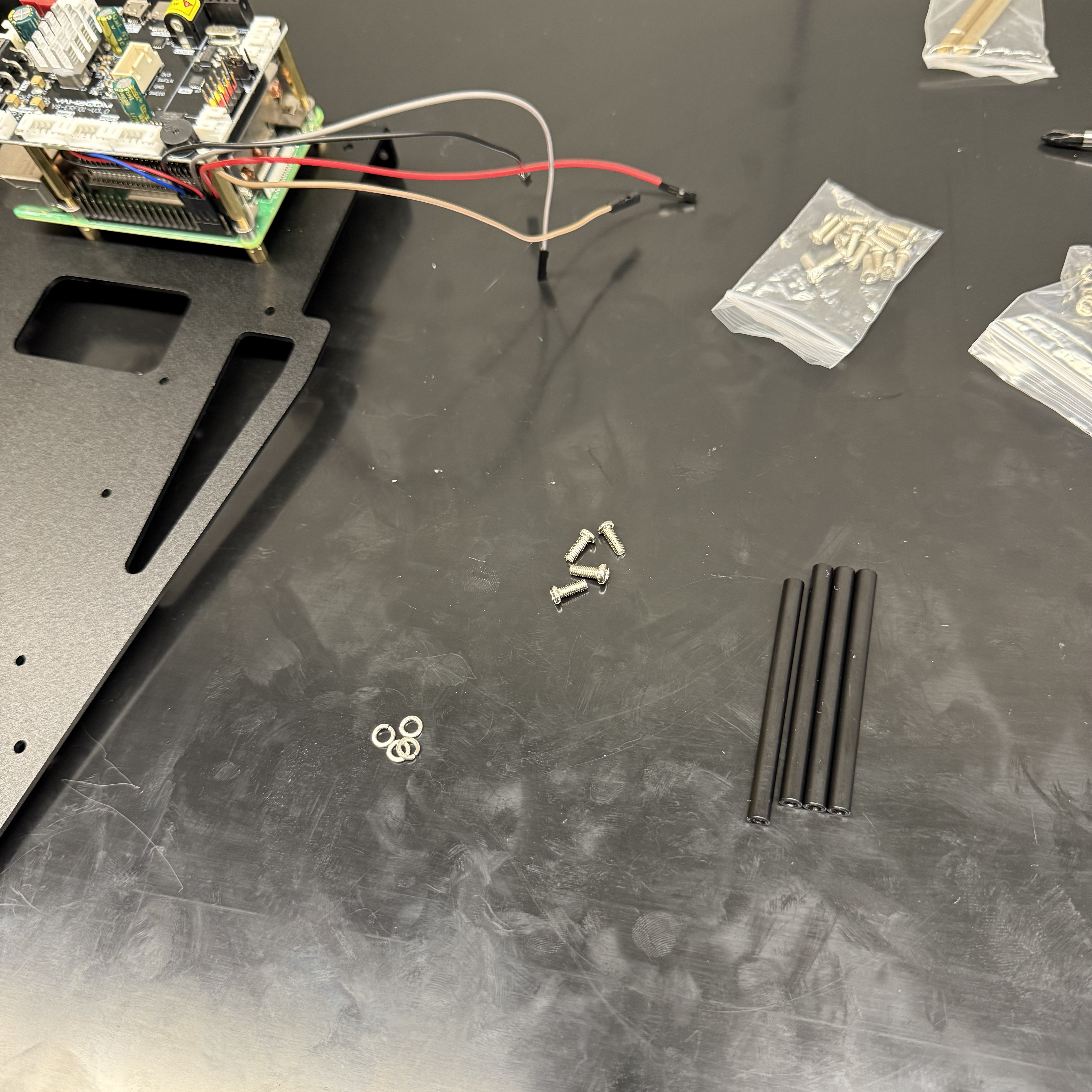 |
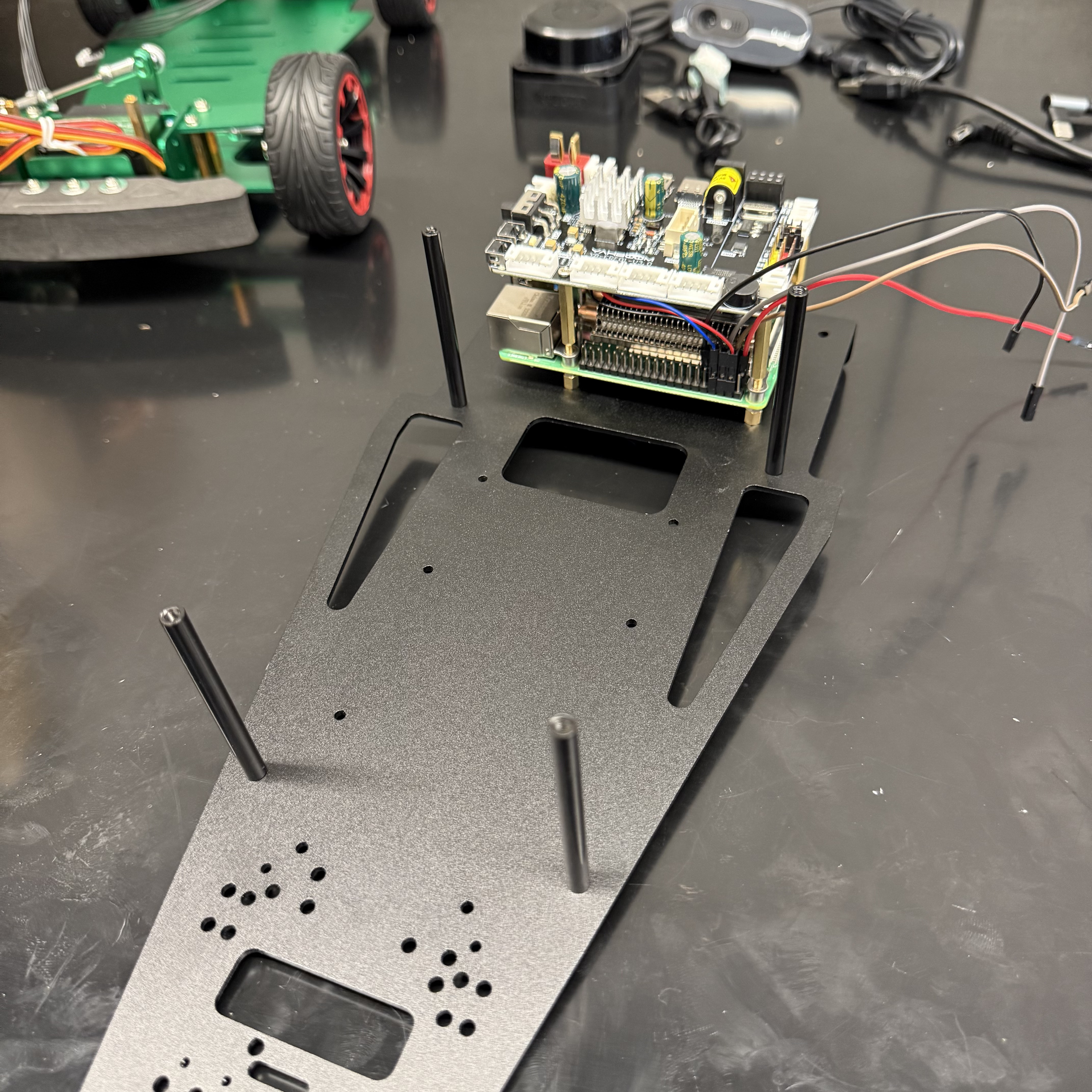 |
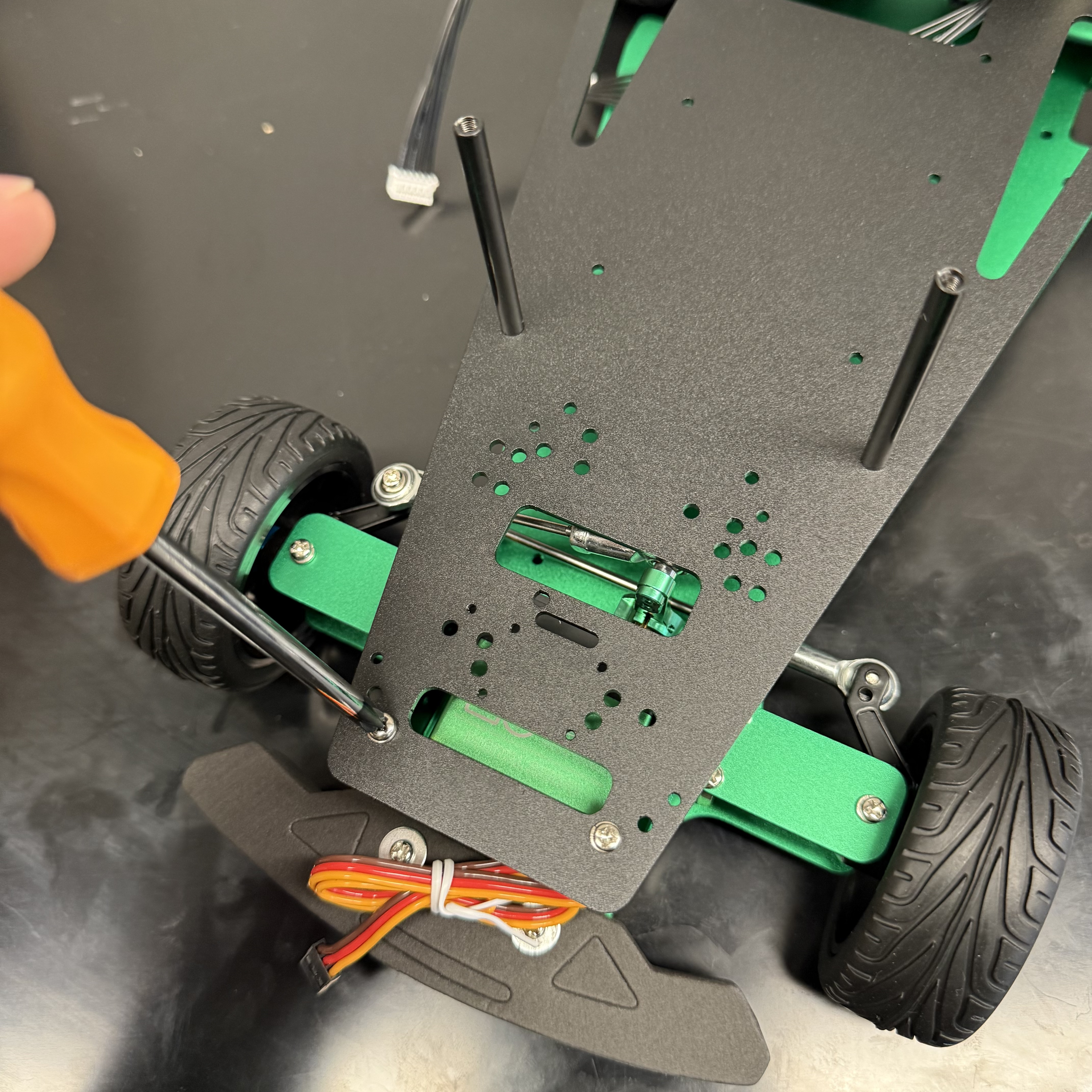
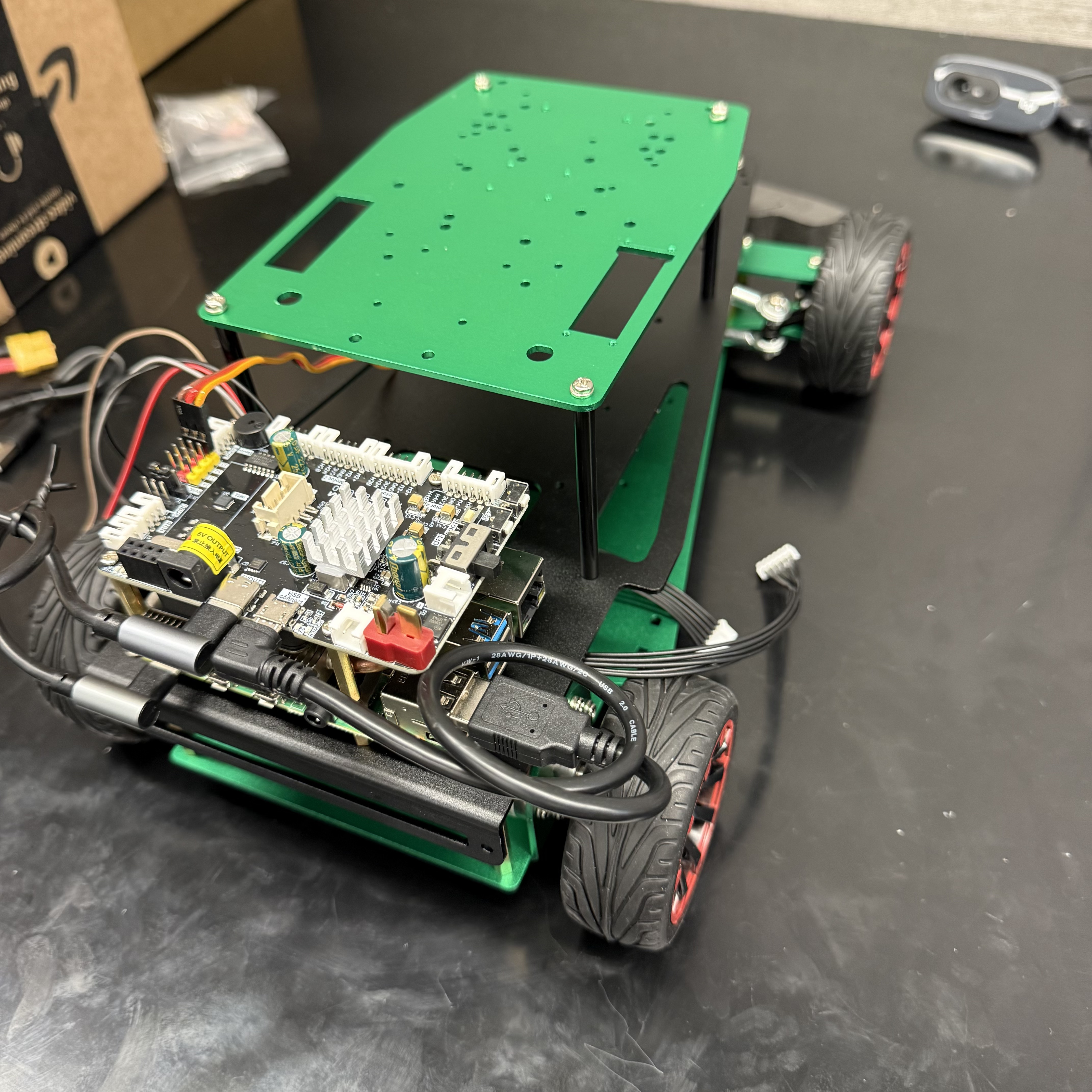
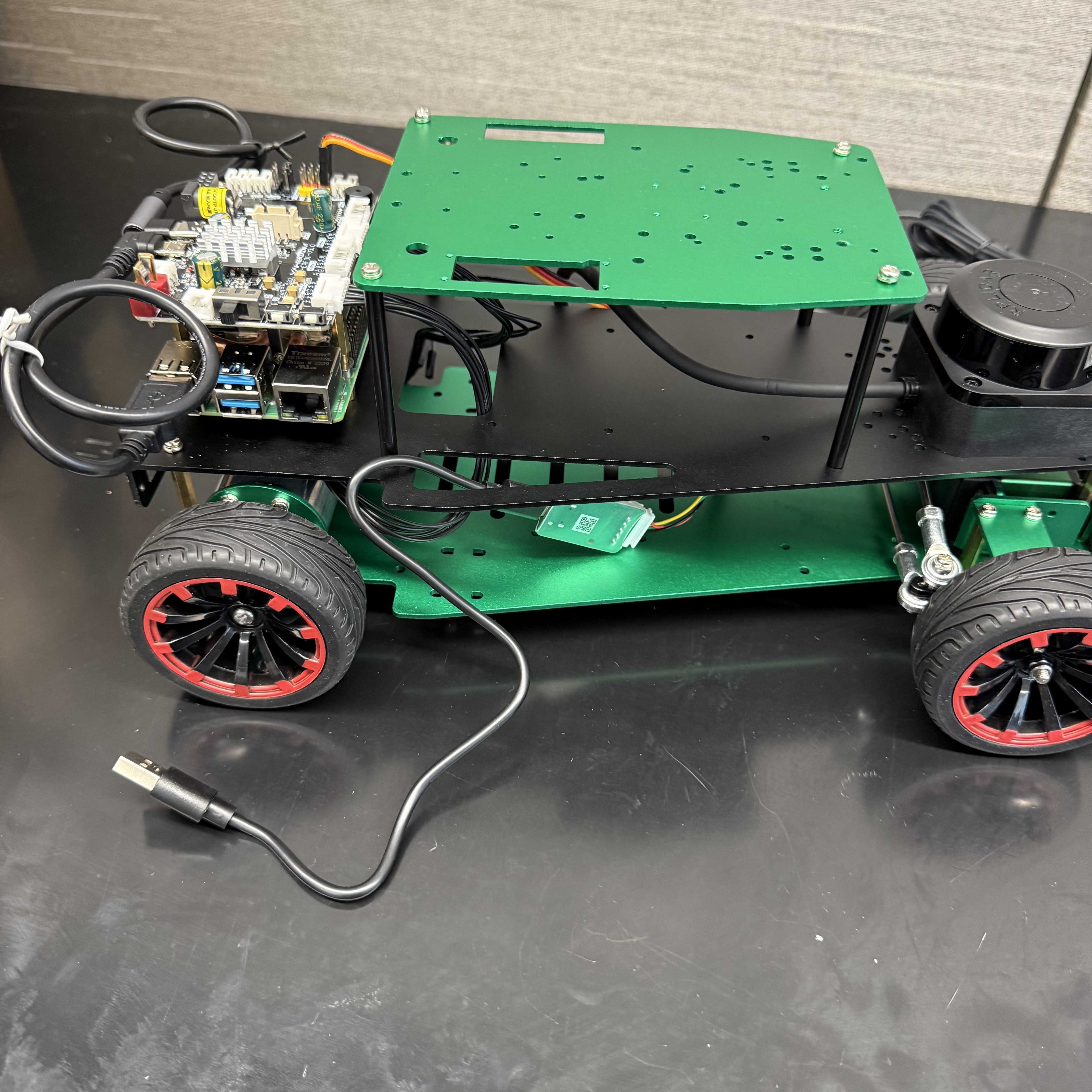
Place the black plate on top of the chassis base:
Using 4 x screws and 4 x washers, attach the black plate to the chassis base (from front to back):
| Parts Needed | ||
|---|---|---|
 |
 |
 |
Finally, attach the top plate to the black plate using 4 x screws and 4 x washers:
| Parts Needed | ||
|---|---|---|
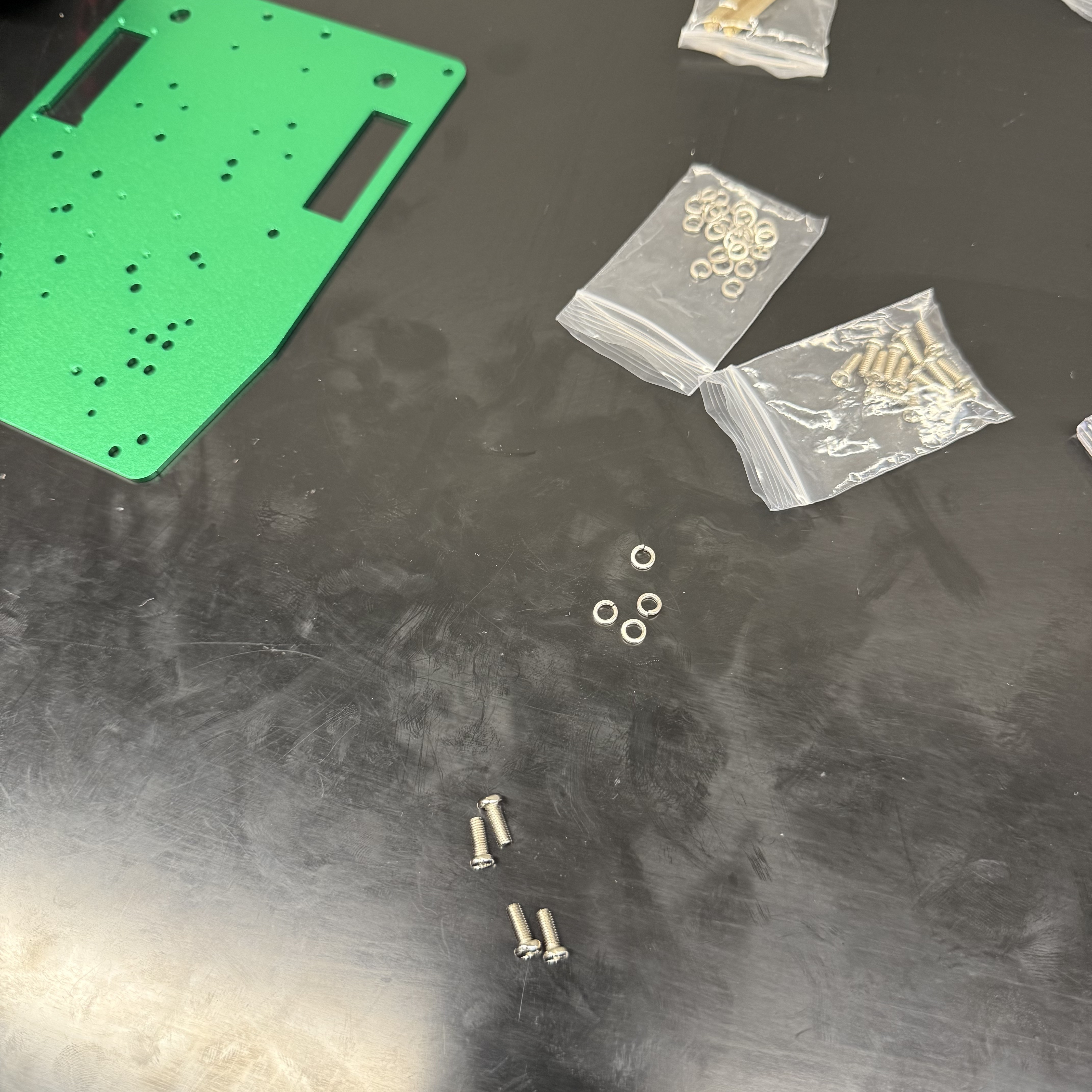 |
 |
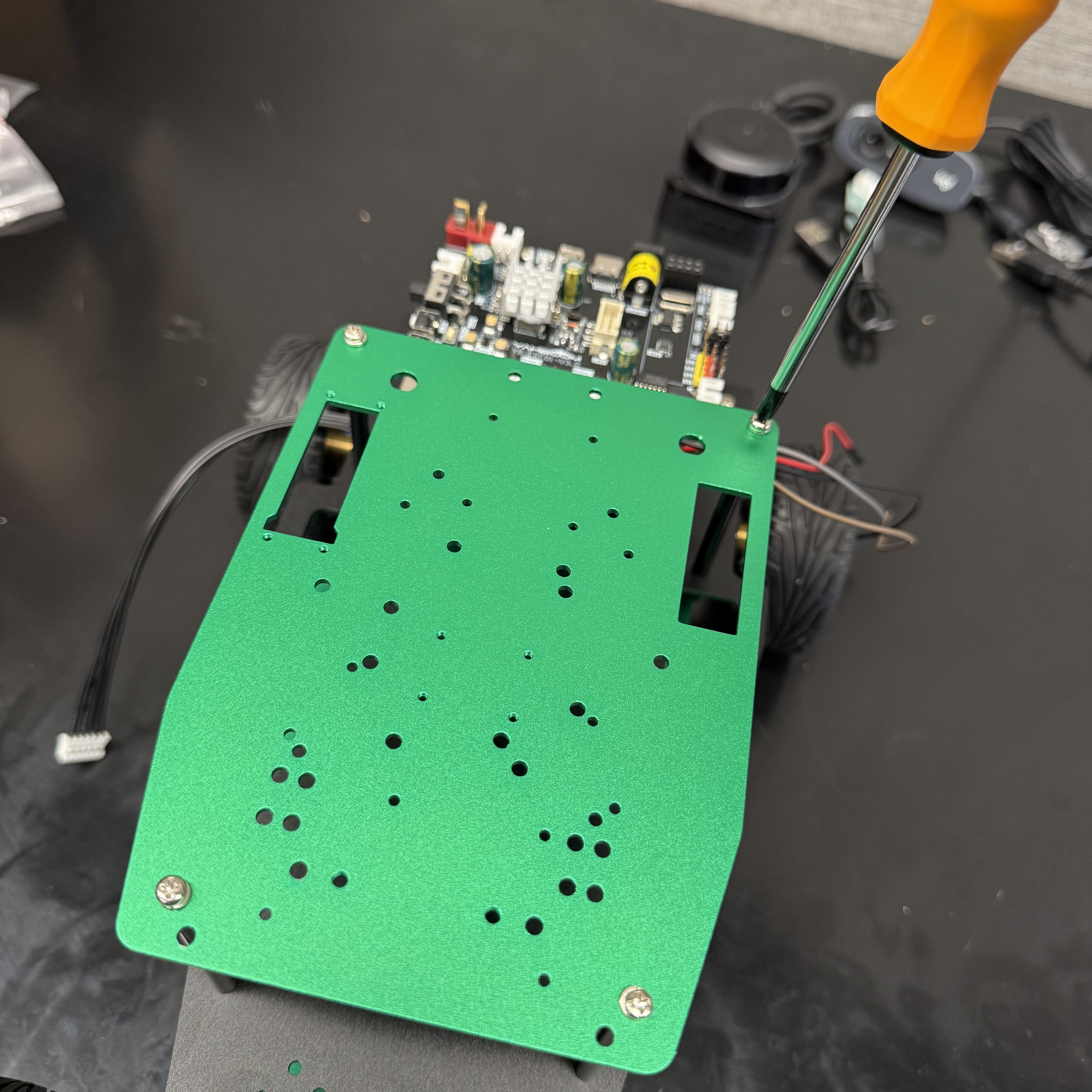 |
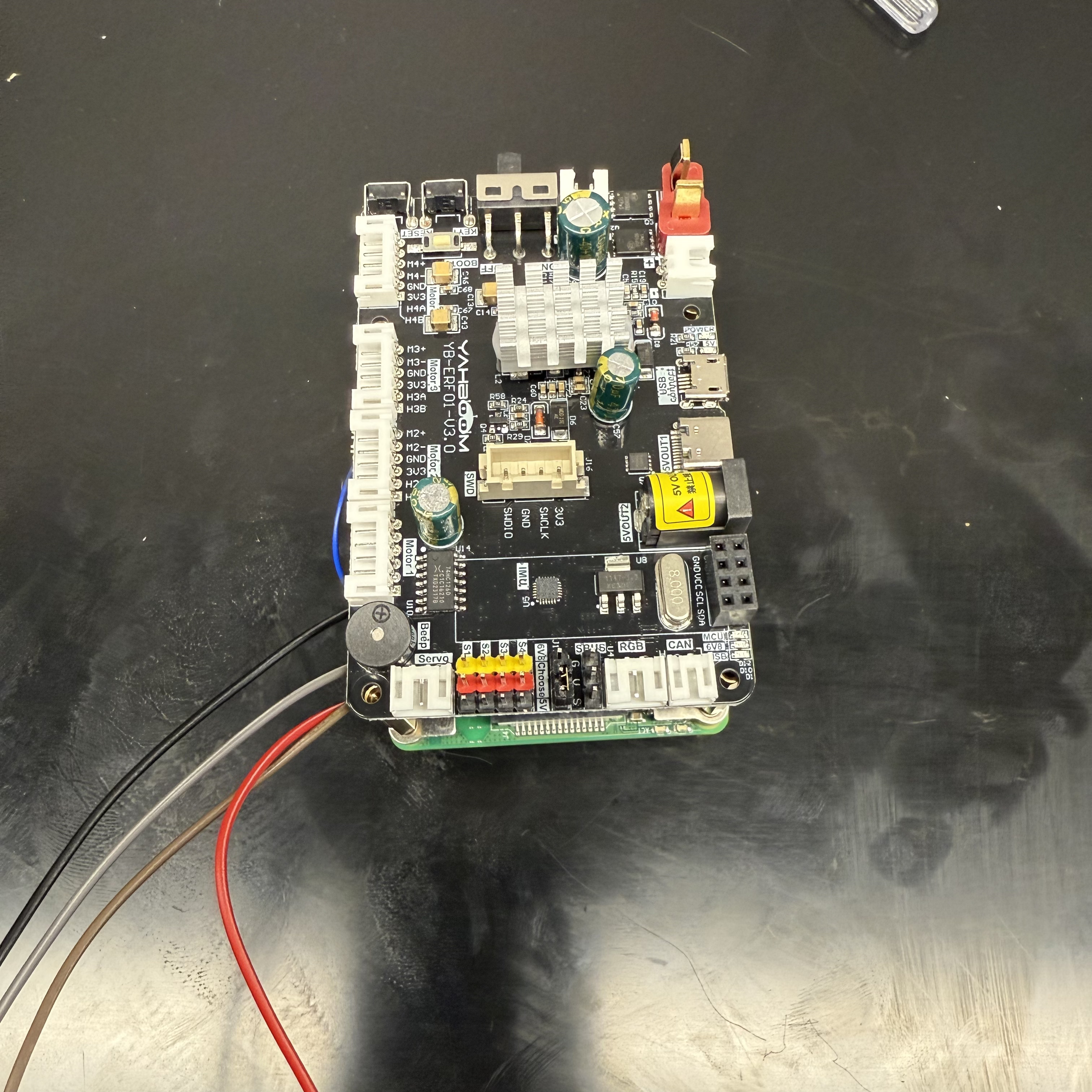
Step 3: Wiring
3.1 Motor Wiring
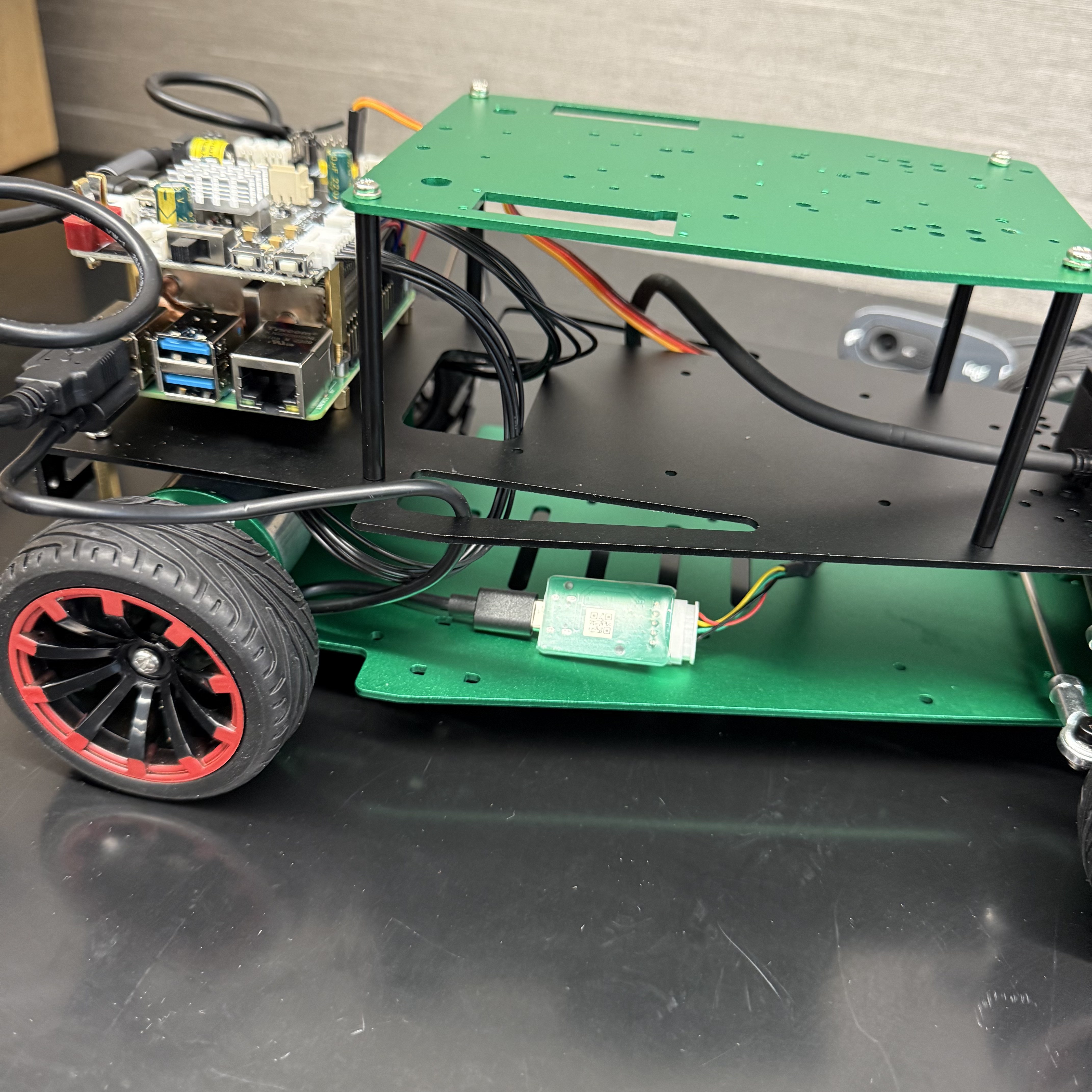
Pass the servo cable through the holes and connect it to the STM Board:
 |
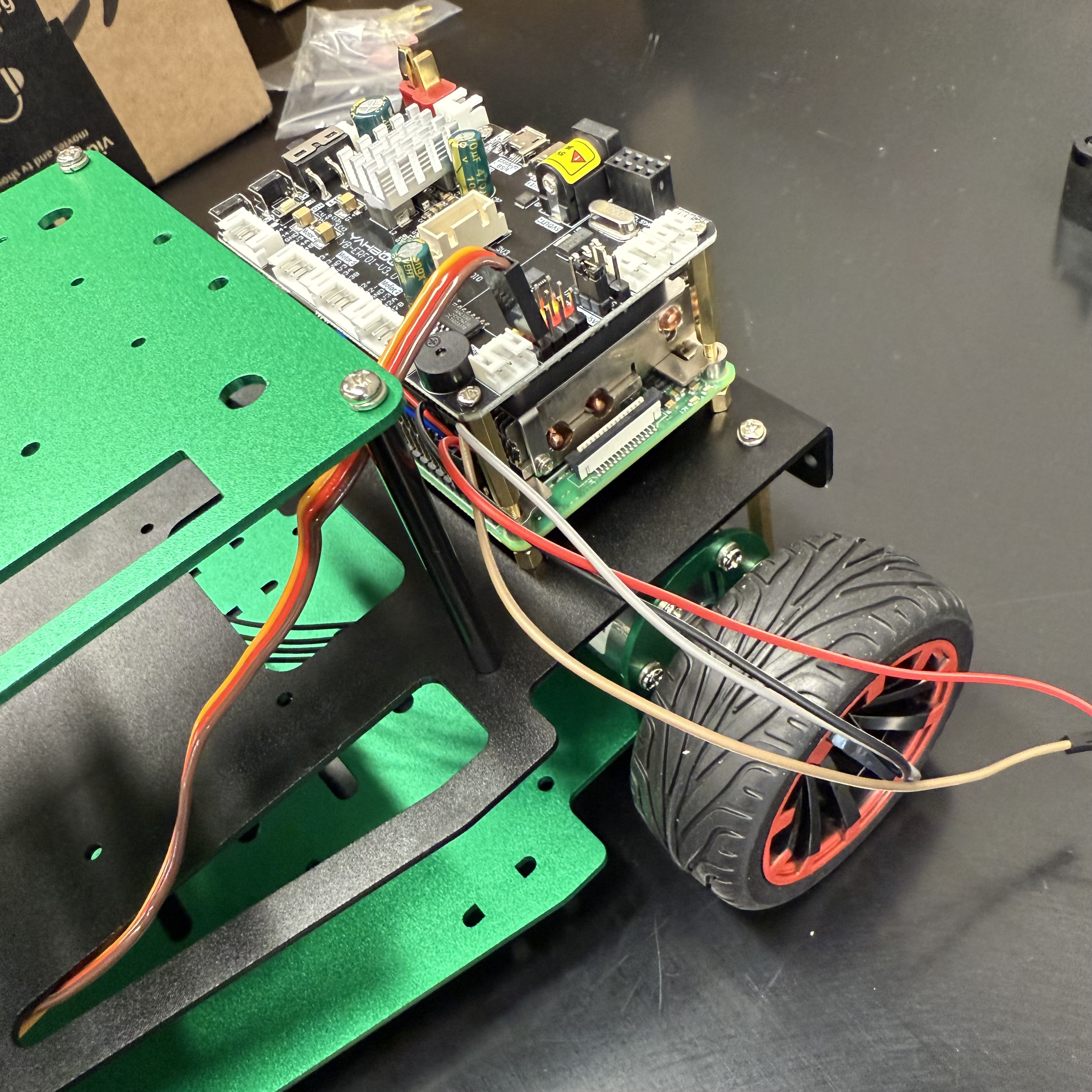 |
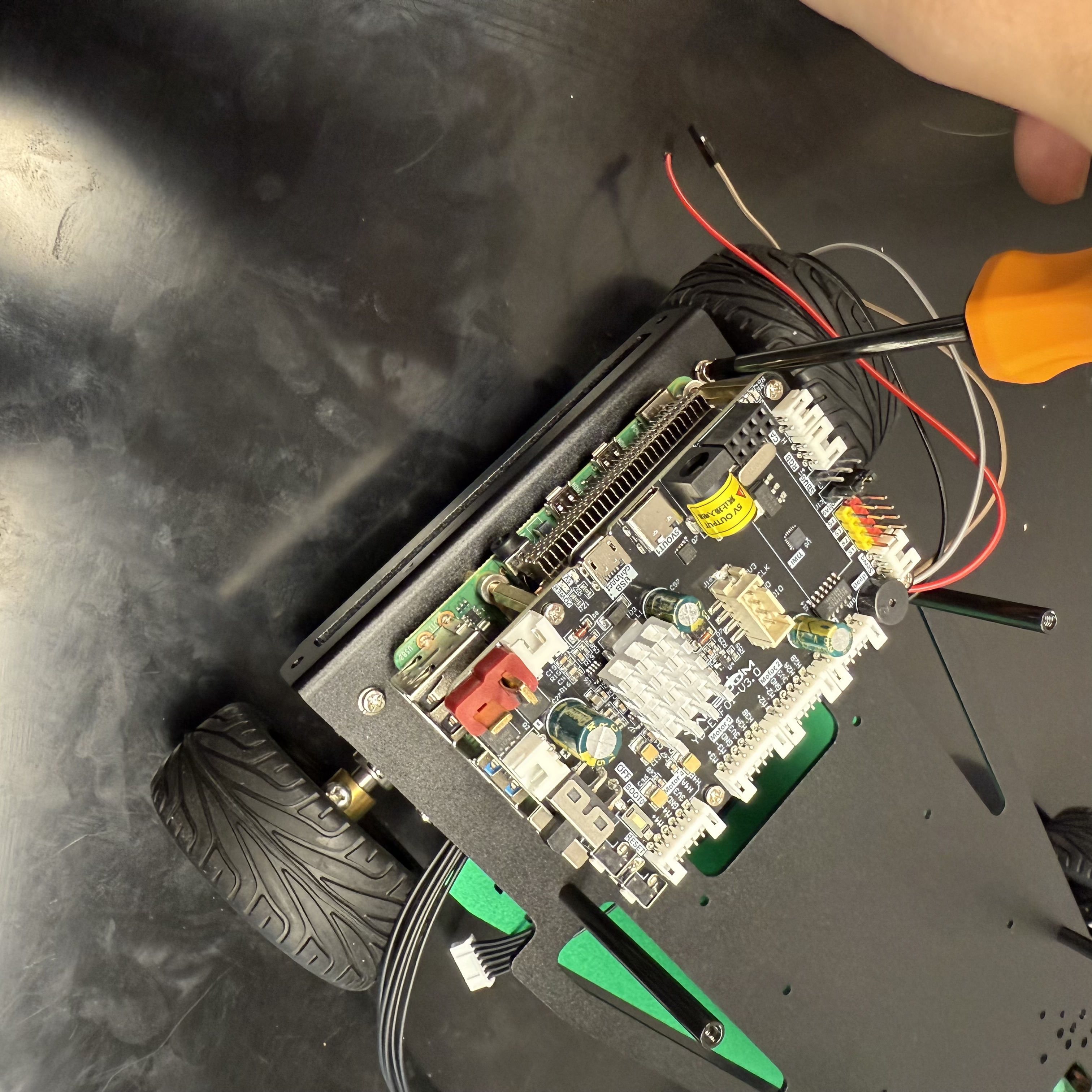
Connect the Raspberry Pi 4 with the STM Board (for power):
 |
 |
Connect the Raspberry Pi 4 with the STM Board (for communication):
 |
 |
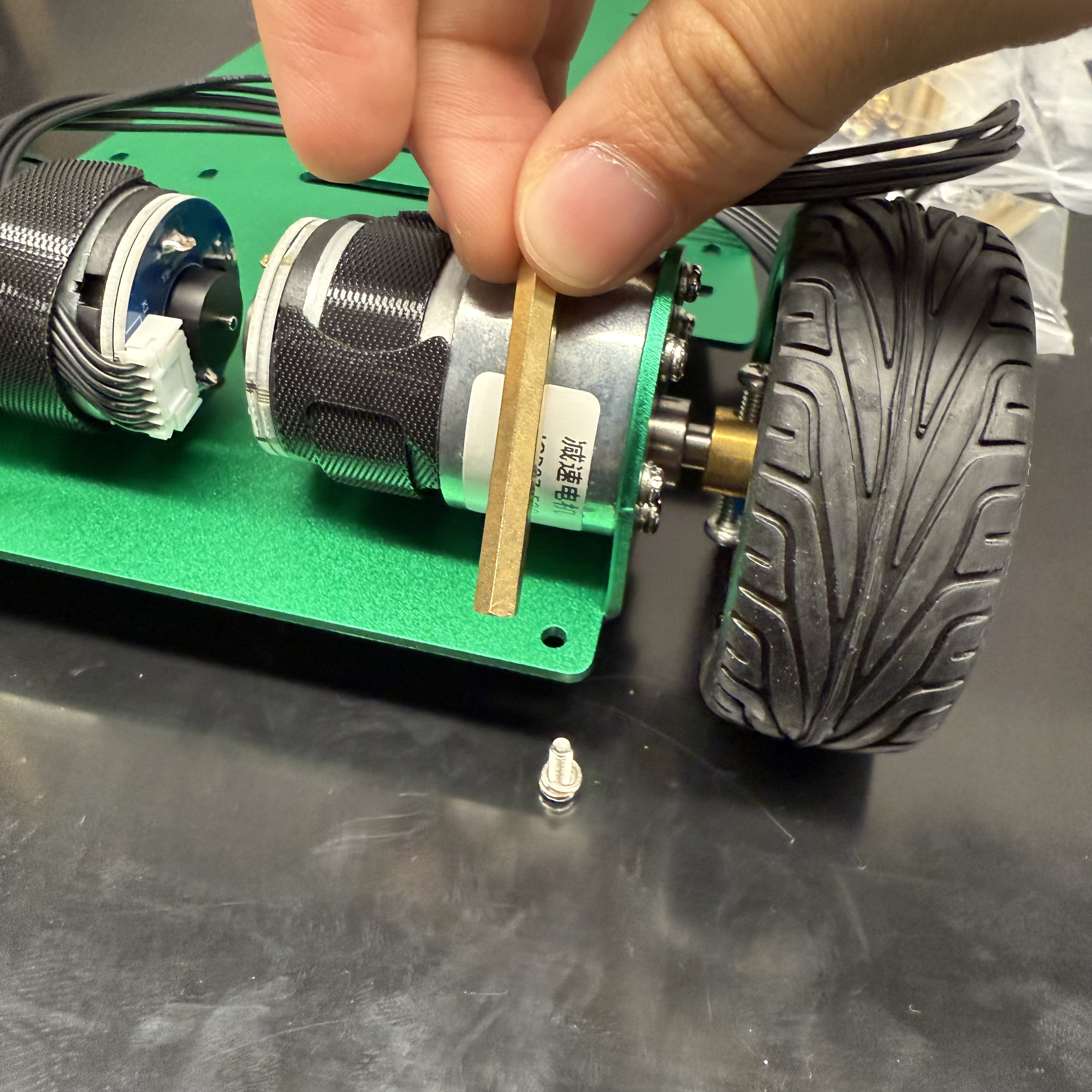
Pass the motor cables through the holes and connect them to the STM Board:
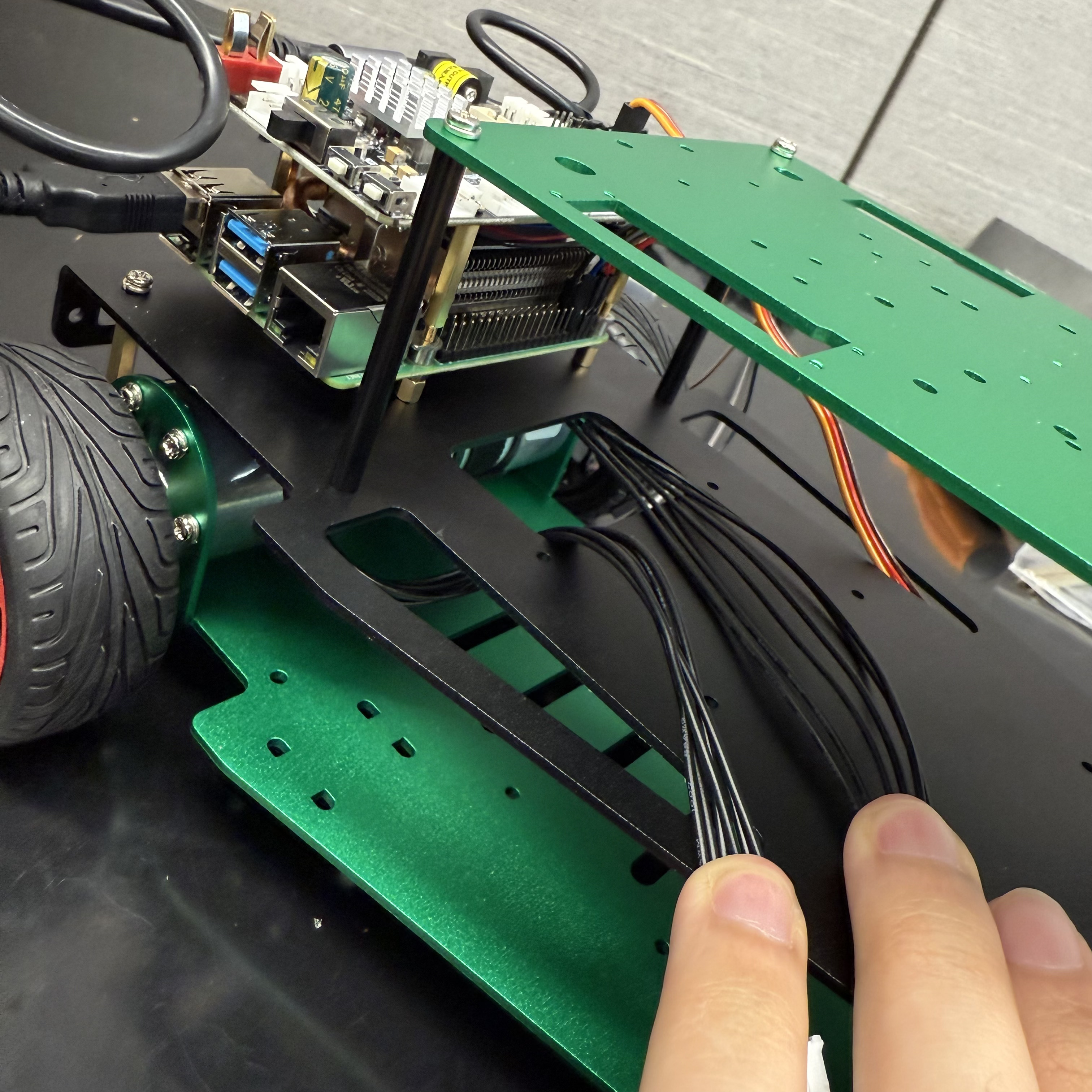 |
 |
 |
⚠️ Right motor -> Motor 4, Left motor -> Motor 2
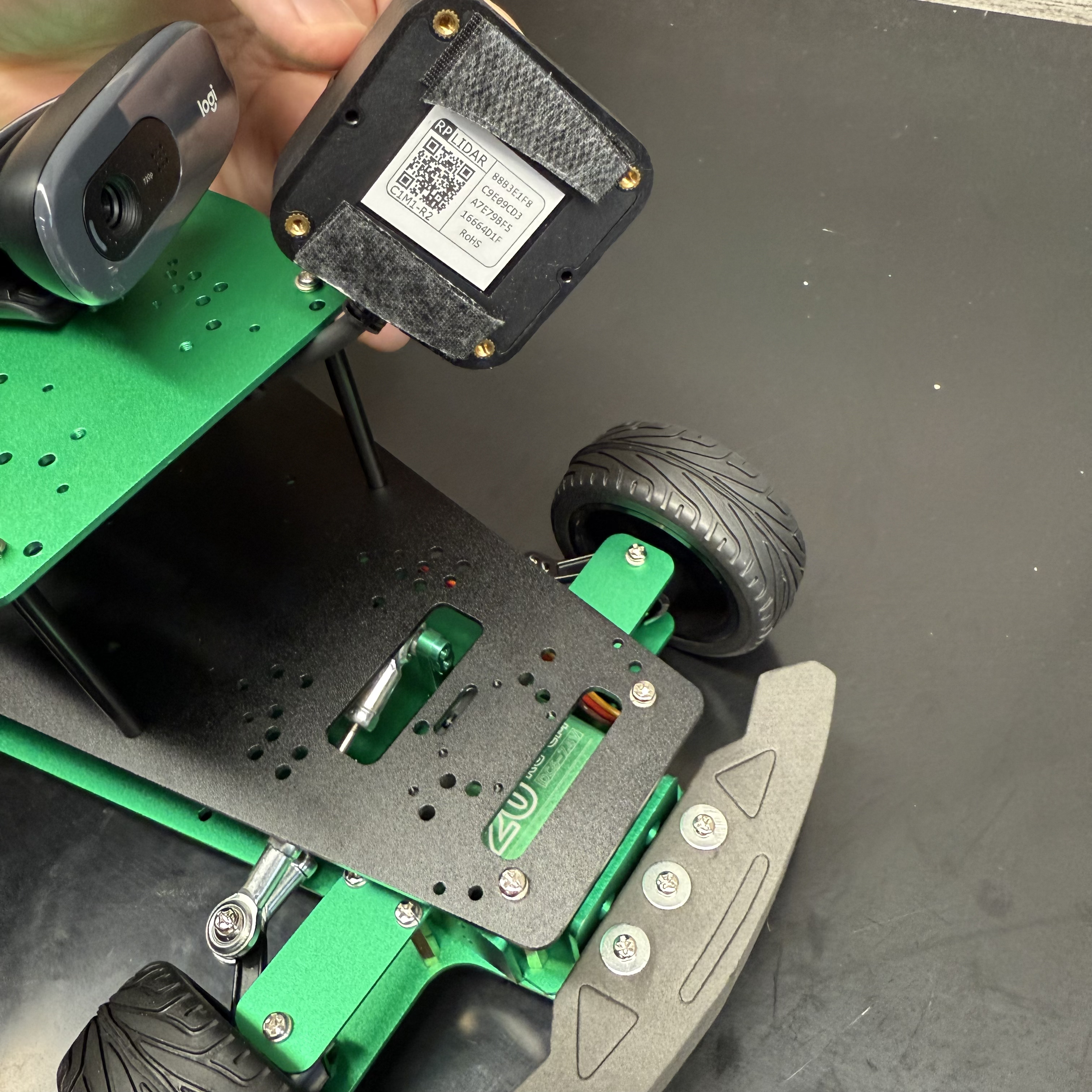
3.2 LiDAR Wiring
Place the LiDAR on the Black Plate without mounting it and pass the cable through the holes:
| Parted Needed | ||
|---|---|---|
 |
 |
 |
3.3 Camera Wiring
Place the camera on the top plate and pass the cable through the holes:
Step 4: Camera, LiDAR, and OLED Display Mounting
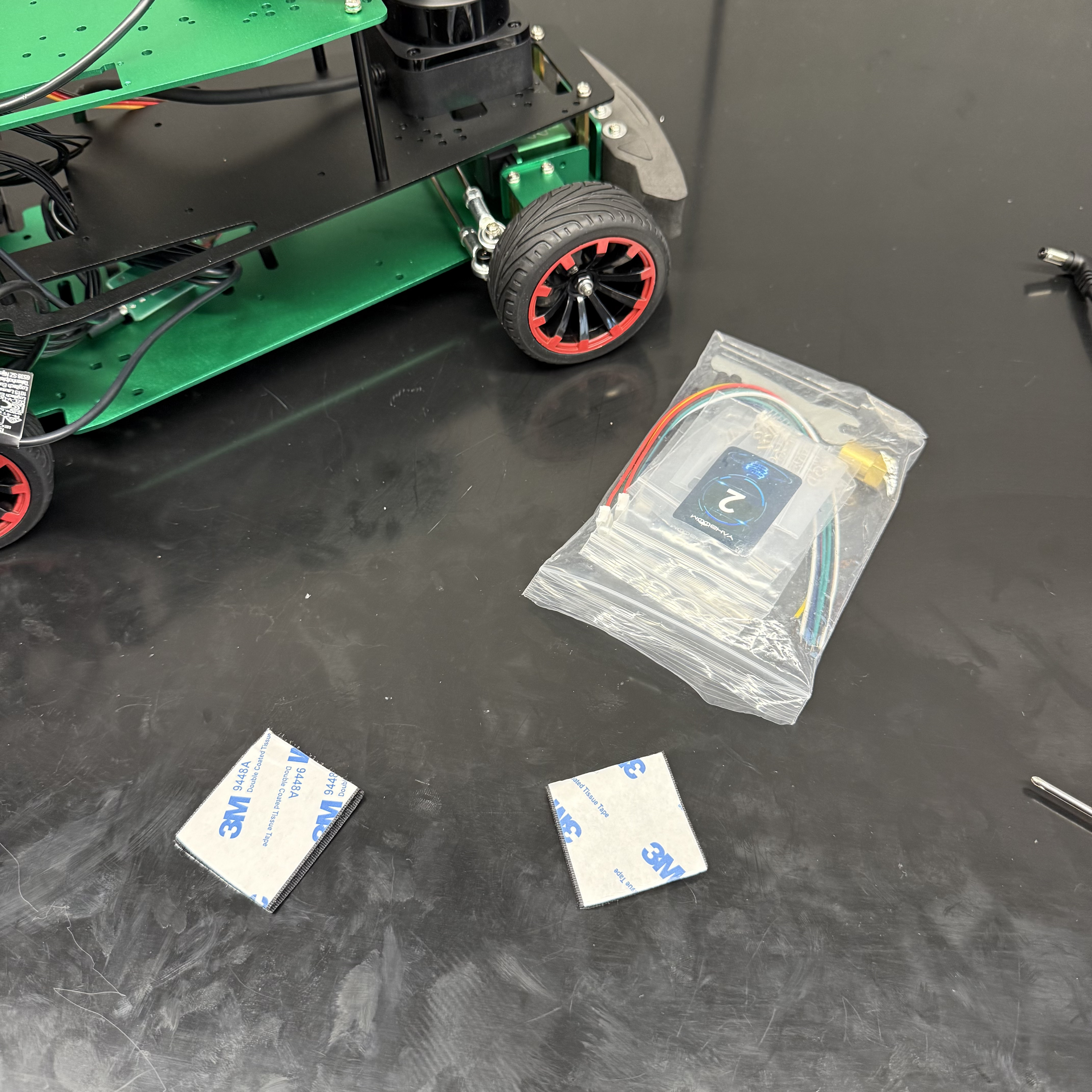
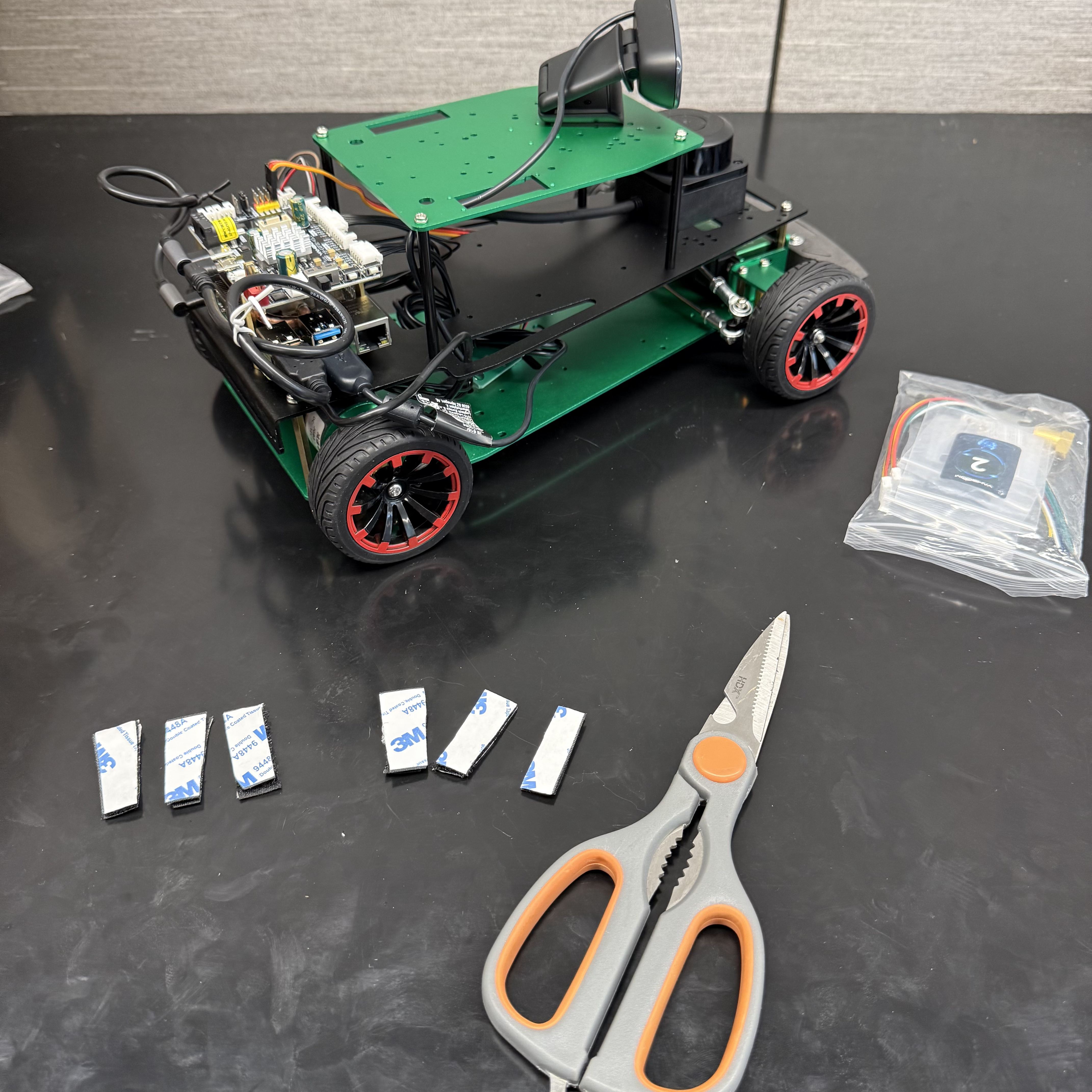
Cut the double-sided tape into pieces:
| Parts Needed | |
|---|---|
 |
 |
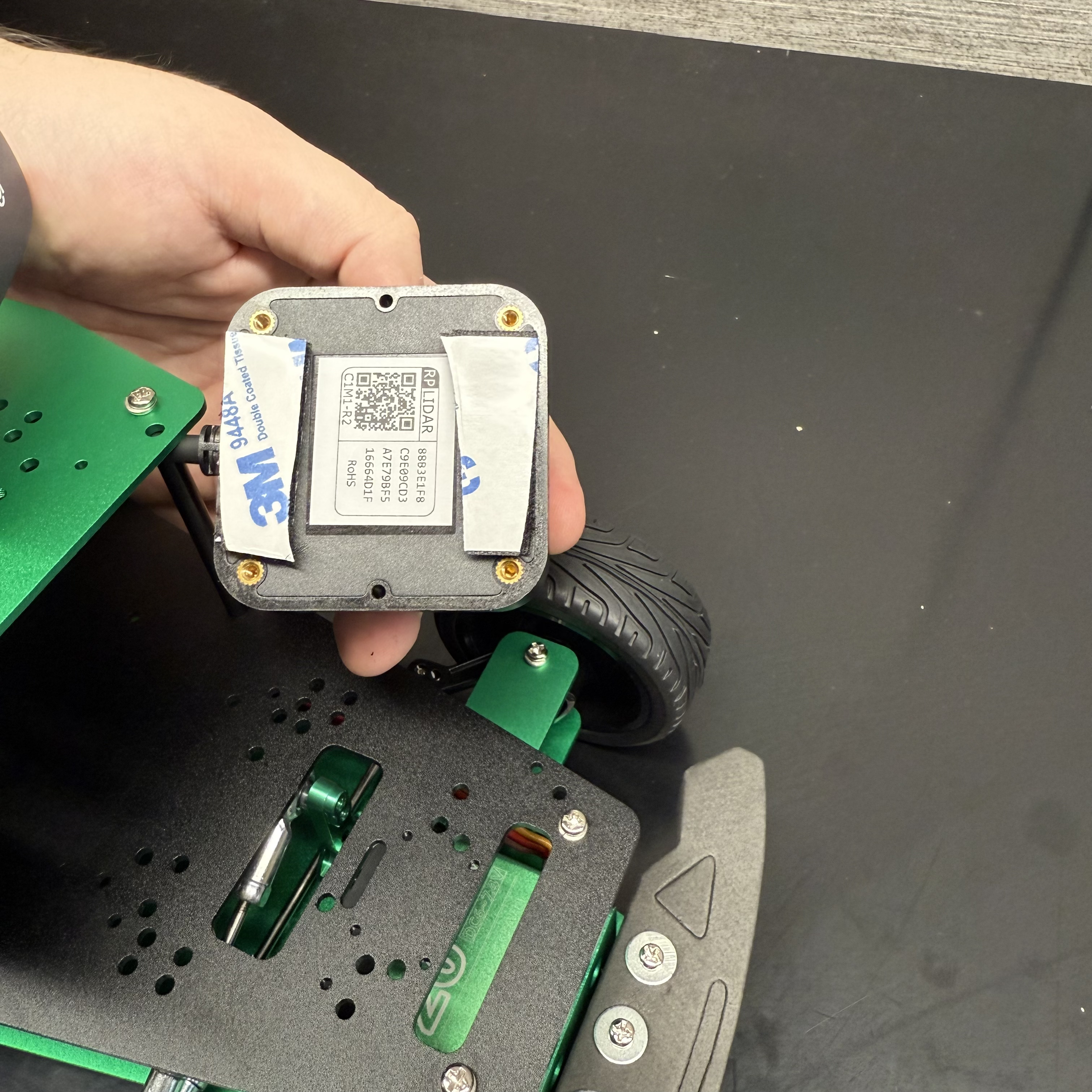
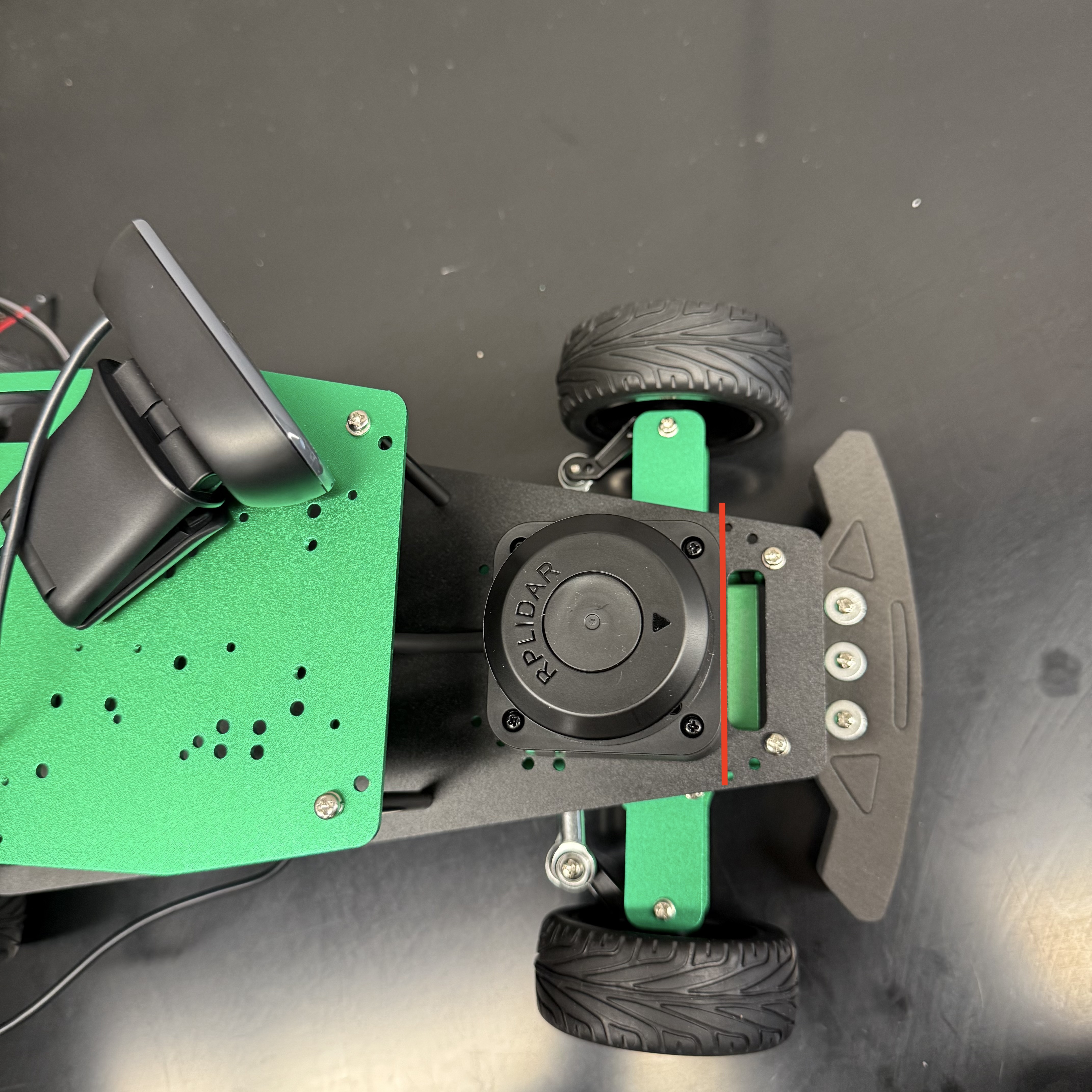
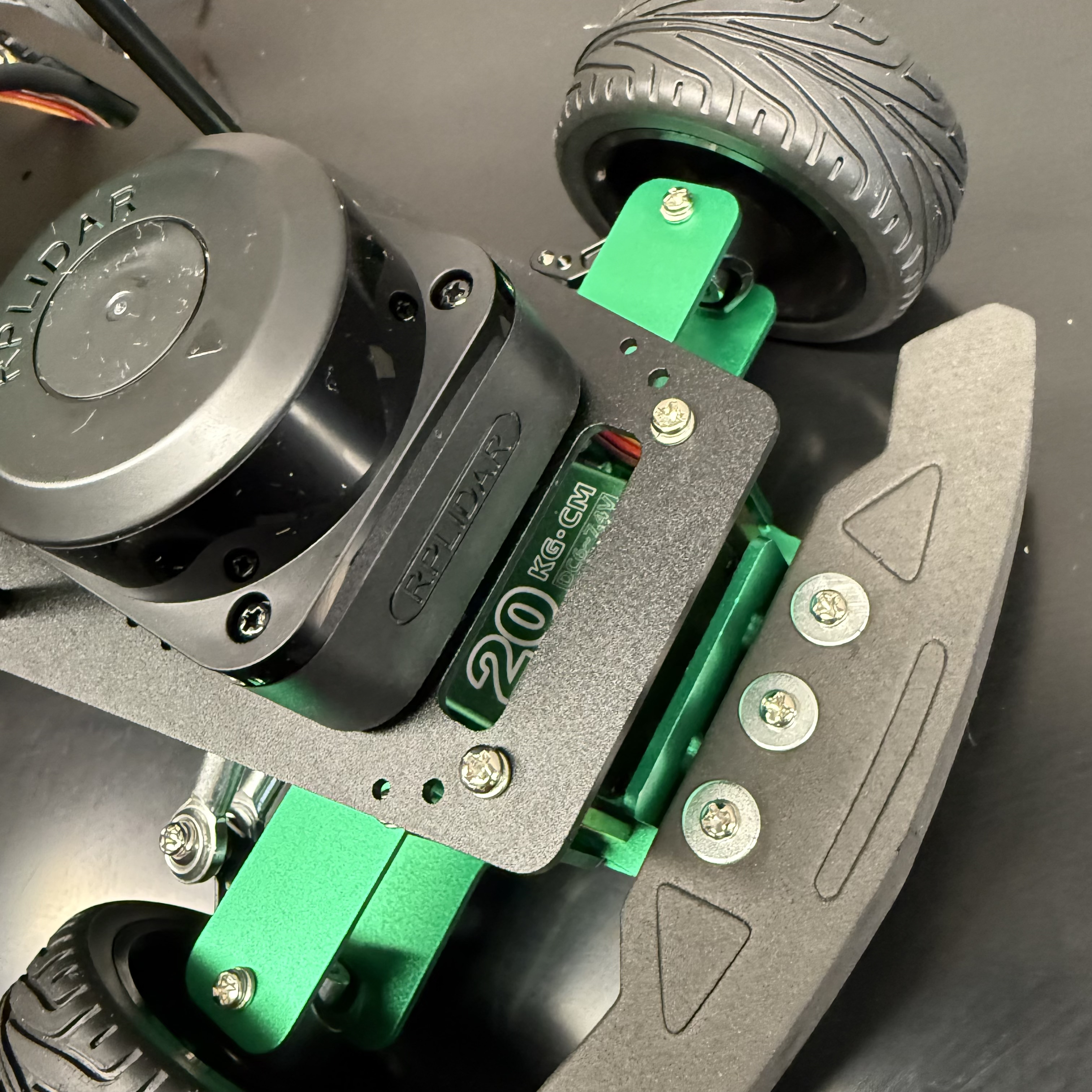
Mount the LiDAR on the black plate:
| Parts Needed | ||
|---|---|---|
 |
 |
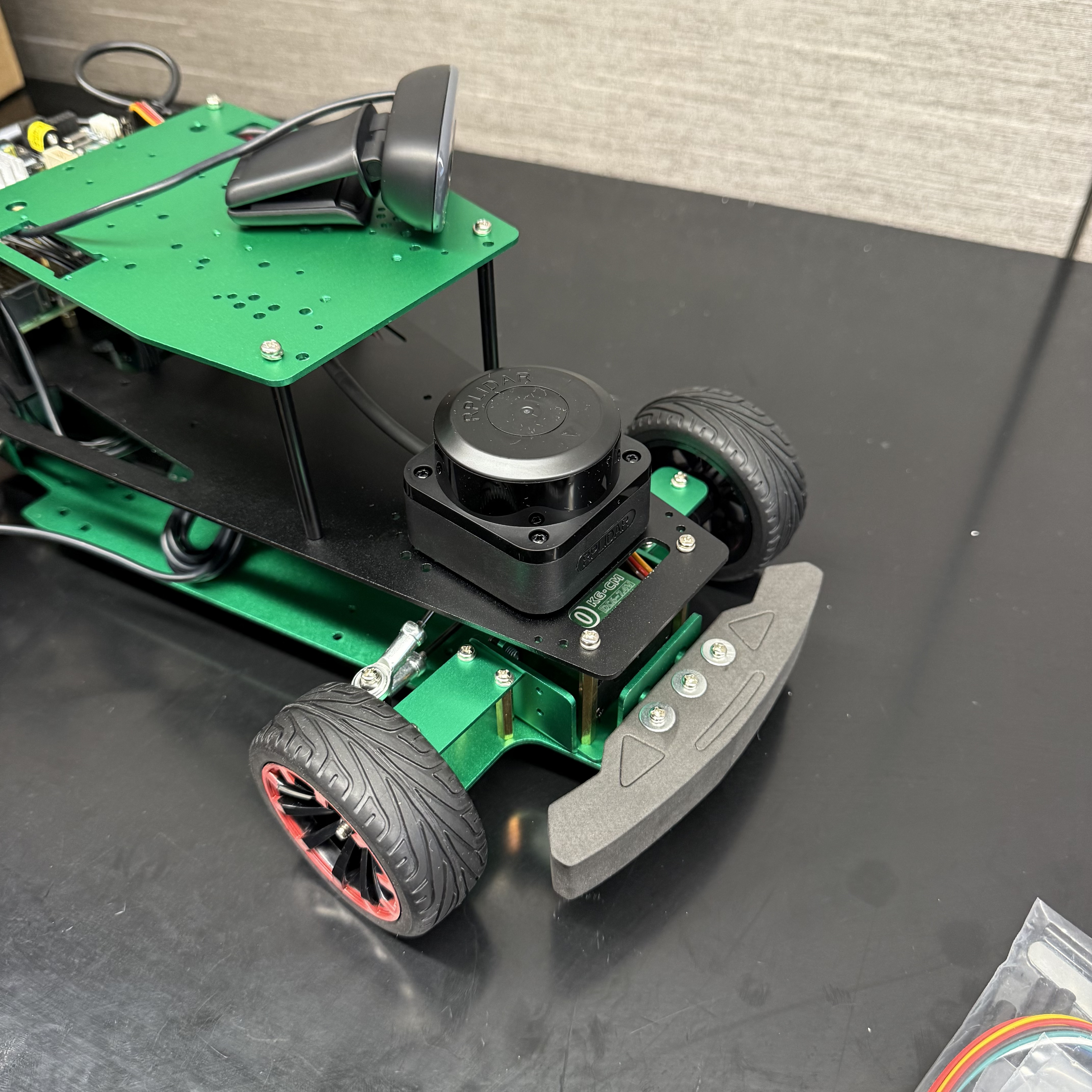 |
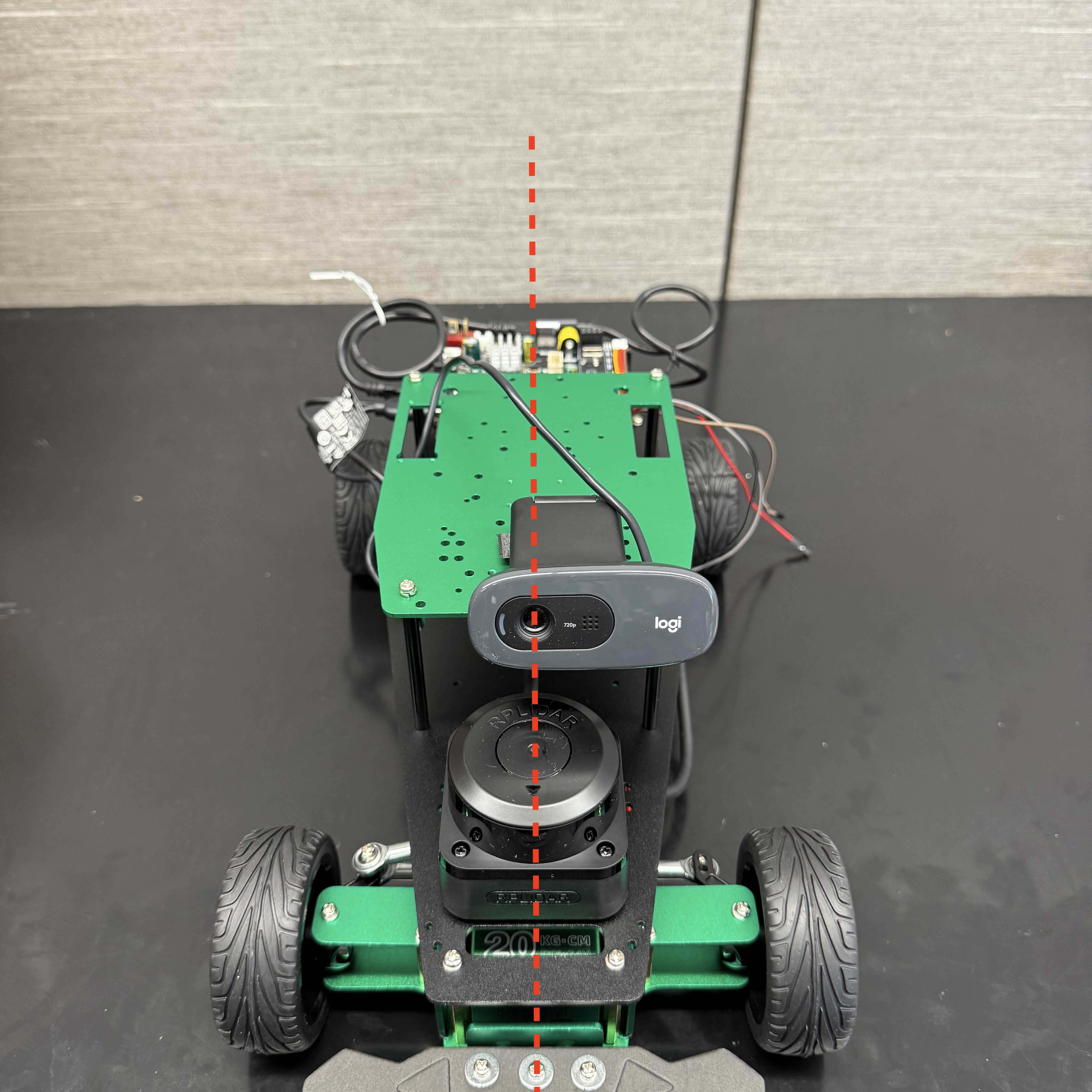
⚠️ Make sure the LiDAR is facing forward and the front edge is aligned as shown in the image.
Mount the camera on the top plate:
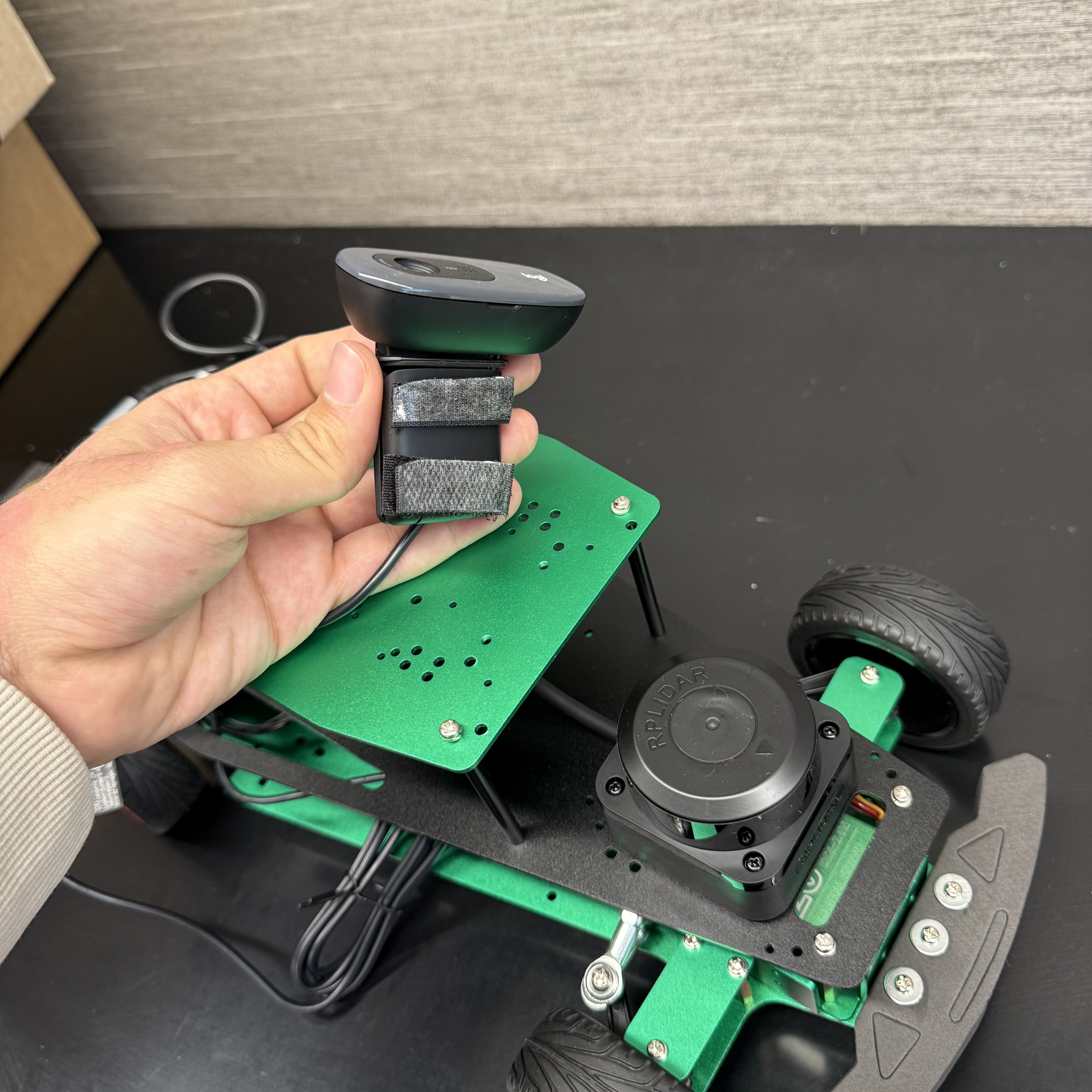 |
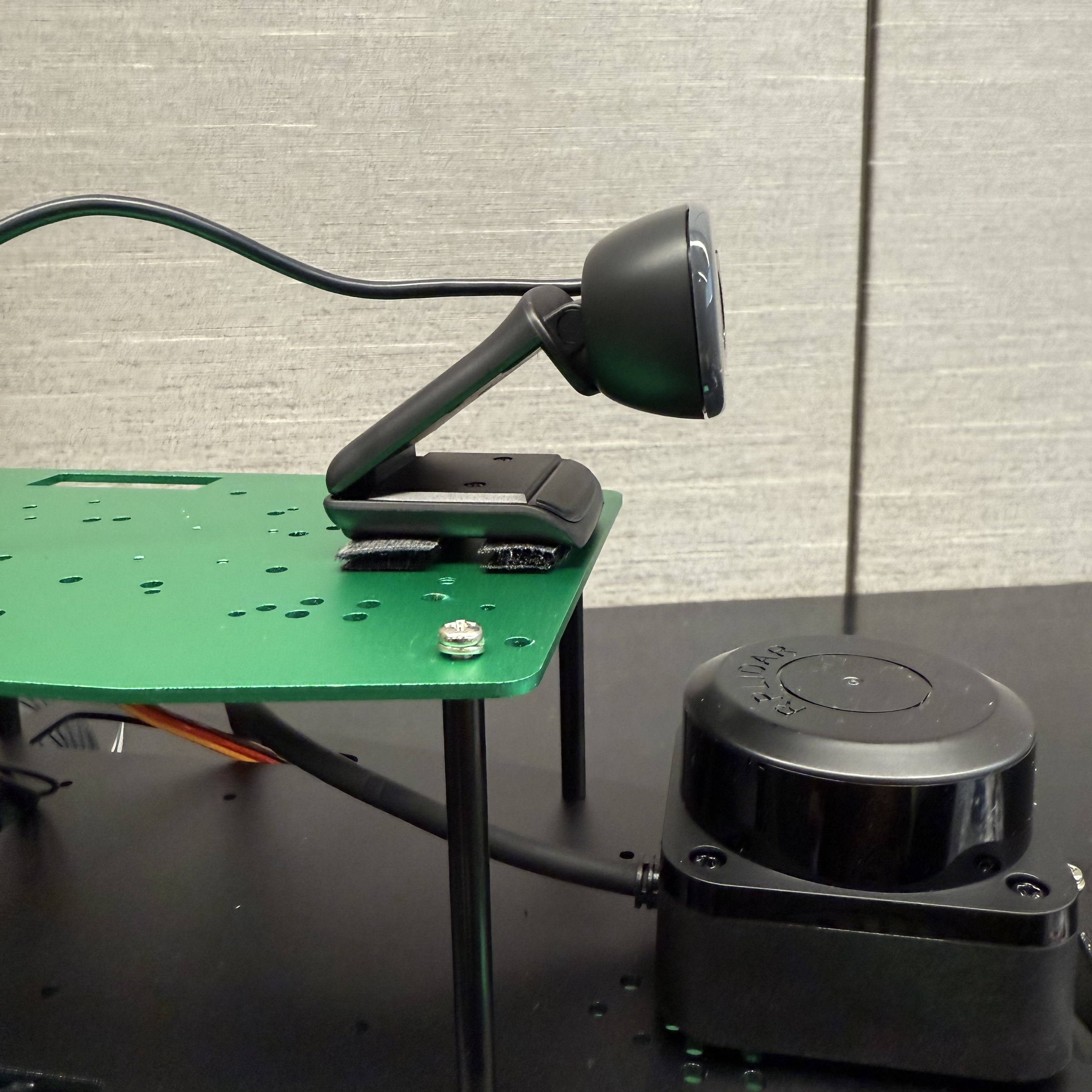 |
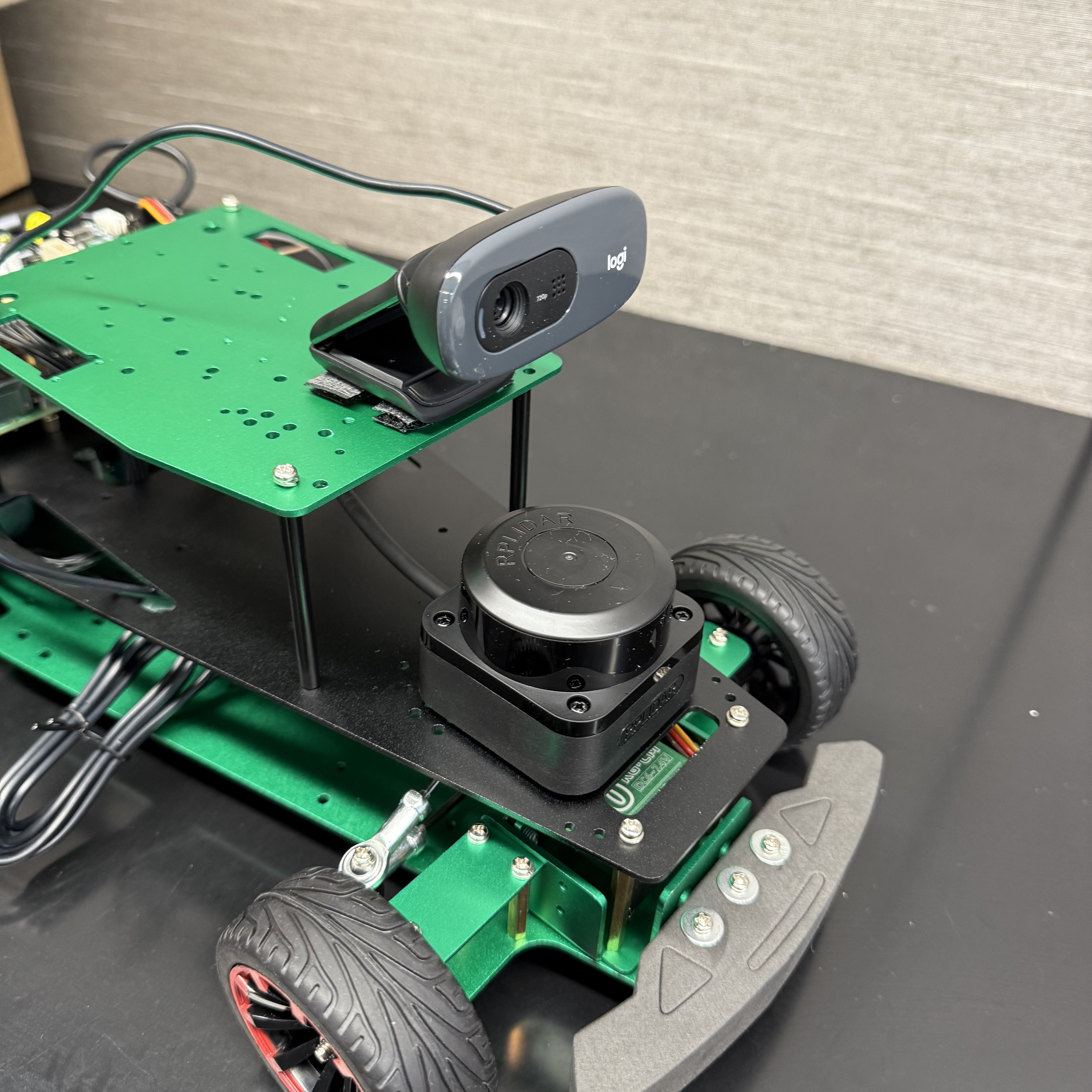 |
⚠️ Insure that the camera lens is at the center axis of the robot.
Connect the OLED Display to the Raspberry Pi 4:
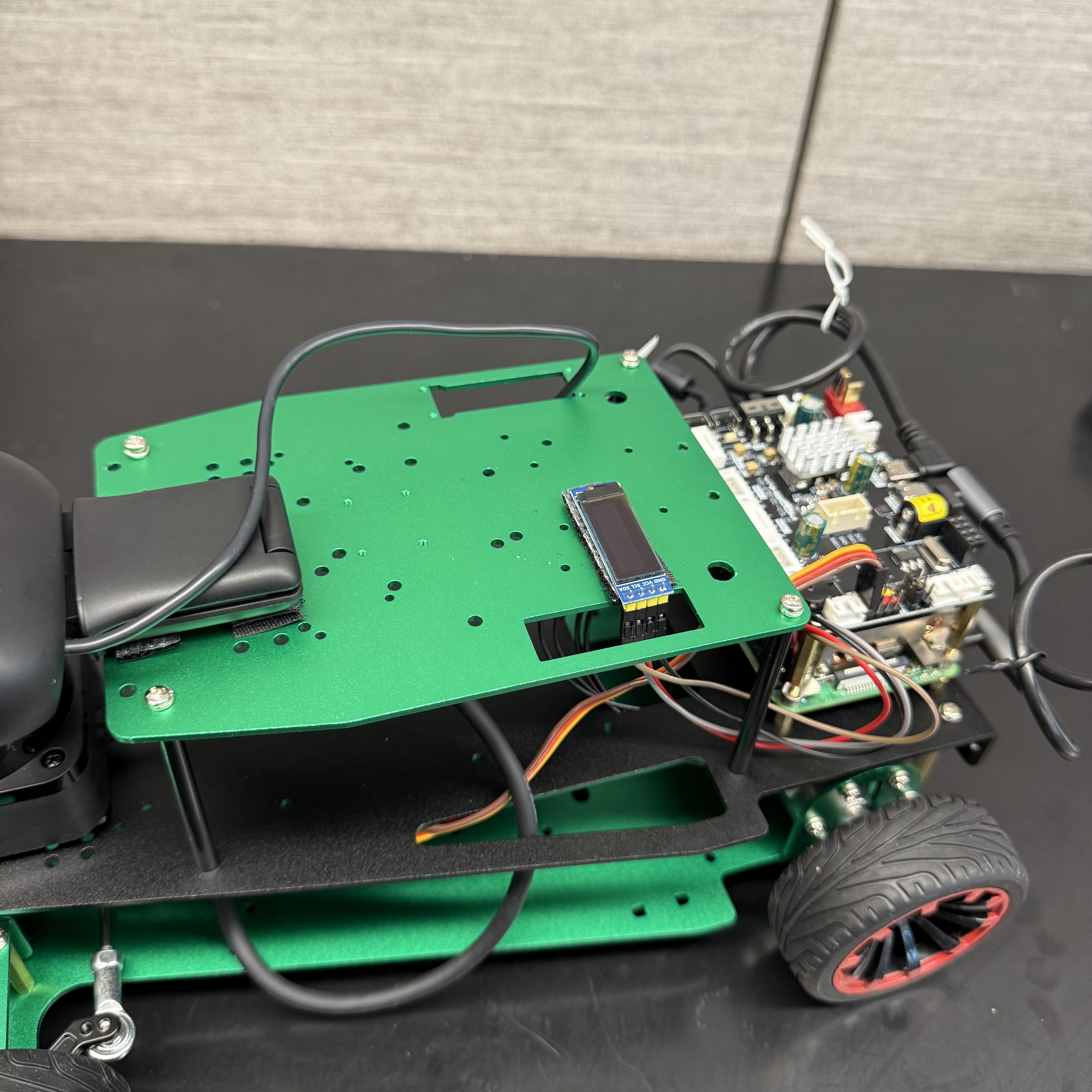
Finally, mount the OLED Display on the top plate:
 |
 |